Magnetic Field Shielding: A Practical Guide to Design and Implementation
Last March, a semiconductor fabrication facility in Wuxi discovered that their new lithography alignment system was producing defect rates three times higher than expected. The machine itself was flawless. The problem was a 400-amp busbar running through the ceiling plenum 12 meters away. Its stray magnetic field, measured at just 0.8 millitesla at the tool location, was enough to deflect the electron beam by nanometers. The engineering team had specified vibration isolation, temperature control, and cleanroom particulate levels to the fourth decimal. Nobody thought about magnetic field shielding.
That oversight cost the facility four months of remediation and a six-figure shielding retrofit. It also illustrates a pattern repeated across industries: magnetic field shielding is treated as an afterthought rather than a core engineering requirement.
You already know that stray magnetic fields cause problems. Sensor drift, signal noise, equipment malfunction, and regulatory non-compliance all trace back to uncontrolled magnetic environments. What you need is a practical understanding of how magnetic field shielding works, when it is necessary, and how to design shielding systems that perform reliably without overengineering the solution.
This guide covers the physics of magnetic field shielding, the critical differences between DC and AC shielding requirements, geometry and material strategies that maximize effectiveness, and the manufacturing considerations that determine whether a shielding design succeeds or fails in production. Whether you are protecting a precision instrument, enclosing a power transformer, or designing an EV motor housing, the principles here will help you specify the right shielding approach.
The Physics Behind Magnetic Field Shielding
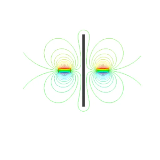
Magnetic field shielding does not work like a solid wall blocking rain. Magnetic flux lines are continuous loops that cannot be stopped or destroyed. Instead, shielding redirects those flux lines through a preferential path that bypasses the sensitive region you want to protect.
How Flux Redirection Works
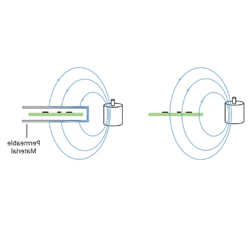
When a magnetic field encounters a high-permeability material, the flux lines concentrate inside that material rather than passing through the air-filled cavity behind it. The shield essentially offers the magnetic equivalent of a low-resistance bypass. Field lines enter the shield wall on the side facing the source, travel through the material, and exit on the far side, looping back to complete their path. The region inside the shield experiences a dramatically reduced field.
This redirection depends on two factors working together: the shield material's relative permeability and the geometry of the enclosure. A material with permeability of 10,000 means the flux prefers traveling through that material 10,000 times more than through air. But if the enclosure has gaps, seams, or openings, flux leaks through those discontinuities regardless of how good the material is.
The Role of Permeability
Relative permeability quantifies how much a material amplifies magnetic flux compared to vacuum. Air has a permeability of approximately 1. High-permeability shielding materials range from a few hundred for low-carbon steel to over 100,000 for properly annealed mu-metal.
Electromagnetic pure iron in DT4C grade achieves relative permeability above 10,000 with saturation induction around 2.15 Tesla. This combination provides strong shielding across a broad range of field strengths. The high saturation point is particularly important because it determines the maximum field the shield can handle before losing effectiveness.
When Rajiv Sundaram designed magnetic enclosures for a series of high-current switching power supplies, he initially specified mu-metal shields based on published permeability data. The prototypes performed well on the bench with low-level test fields. In the actual operating environment, where switching transients generated peak fields exceeding 50 millitesla, the mu-metal saturated intermittently. Switching to electromagnetic pure iron shields with 2.15 Tesla saturation eliminated the intermittent failures entirely.
Looking for high-permeability pure iron with verified magnetic properties? Browse our DT4C electromagnetic pure iron specifications and request a material certificate.
Shielding Effectiveness Measurement
Engineers express shielding effectiveness in decibels, calculated as 20 times the logarithm of the ratio between the unshielded and shielded field strengths. A 20 dB reduction means the field drops to one-tenth. A 40 dB reduction means one-hundredth. Achieving 60 dB or more requires careful attention to material selection, thickness, geometry, and seam design.
The formula for an ideal spherical shield provides a useful starting estimate:
SE = 20 log(1 + 2μt/3r)
Where μ is relative permeability, t is wall thickness, and r is shield radius. Real enclosures deviate from this ideal, but the formula highlights the key variables: higher permeability, greater thickness, and larger radius all improve shielding effectiveness.
DC Versus AC Magnetic Field Shielding
The frequency content of the magnetic field you need to shield fundamentally changes your design approach. DC and quasi-DC fields require different strategies than AC fields, and broadband environments demand hybrid solutions.
Shielding Static and Low-Frequency Fields
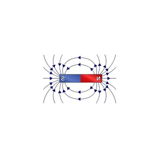
Static magnetic fields, such as those from permanent magnets or DC power busbars, present the purest shielding challenge. The shield must provide a low-reluctance path for the flux to travel around the protected region. Material permeability and thickness dominate performance. Geometry matters enormously because there are no eddy current effects to assist the shielding mechanism.
Earth's magnetic field, approximately 50 microtesla, creates a baseline that affects sensitive magnetometers, electron microscopes, and certain medical devices. Shielding against such weak fields requires materials with very high initial permeability. Mu-metal or annealed nanocrystalline alloys perform best in this regime because their initial permeability exceeds that of pure iron at low excitation levels.
For industrial DC shielding against stronger sources like MRI fringe fields or DC busbars, pure iron's high saturation induction becomes the dominant advantage. The field strength at the shield surface determines whether the material can handle the flux without saturating.
Shielding Alternating Fields
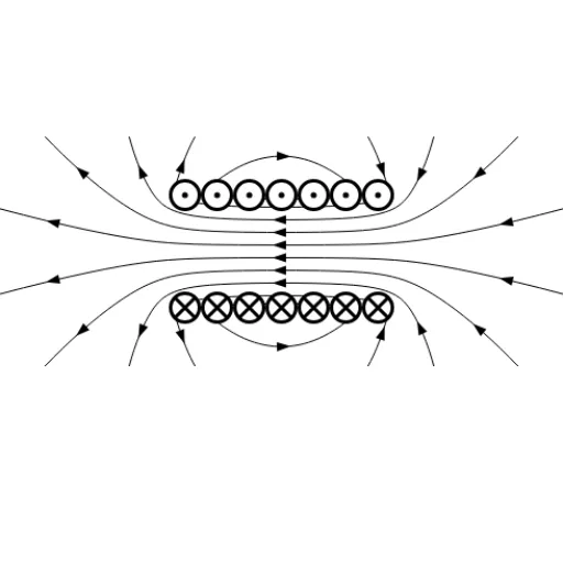
AC magnetic fields introduce additional physics. Changing magnetic fields induce eddy currents in conductive shield materials. These eddy currents generate their own magnetic field that opposes the incident field. At sufficiently high frequencies, eddy current shielding becomes the dominant mechanism, and material conductivity matters more than permeability.
At power line frequencies (50 Hz or 60 Hz), both permeability-driven redirection and eddy current effects contribute to shielding. This makes power frequency shielding a hybrid problem. Silicon steel, with its higher electrical resistivity compared to pure iron, reduces eddy current heating while maintaining reasonable permeability. For this reason, large power transformer shields often use silicon steel laminations rather than solid pure iron plates.
For frequencies above roughly 10 kHz, metallic shields become less effective as eddy currents increasingly block flux penetration. Soft ferrites, with their near-infinite resistivity, serve as absorptive shields at these frequencies. They convert magnetic energy to heat rather than redirecting flux.
Broadband Shielding Strategies
Many real-world environments contain magnetic interference across a wide frequency spectrum. An electric vehicle motor generates fundamental fields at the switching frequency plus harmonics extending into the hundreds of kilohertz. A factory floor might combine 50 Hz power frequency fields with high-frequency noise from variable frequency drives.
Broadband shielding typically combines materials in layers. An outer high-permeability layer handles low-frequency flux redirection. An inner conductive or ferrite layer suppresses higher-frequency components. The air gap between layers further improves performance by preventing the layers from magnetically coupling into a single effective thickness.
Geometry and Enclosure Design for Maximum Effectiveness
Material selection gets the most attention in shielding discussions, but geometry often determines whether a shielding system works in practice. A mediocre material in an excellent enclosure can outperform a premium material in a poorly designed one.
Closed Enclosures Versus Partial Shields
A fully enclosed box or cylinder provides the best shielding because the flux has no gap to leak through. The shield forms a continuous magnetic circuit around the protected region. Opening even a small slot or hole creates a leak path that can dramatically reduce effectiveness.
Partial shields, such as plates placed between a source and a sensitive device, provide directional attenuation but do not block flux arriving from other angles. They work adequately when the interference source location is fixed and known, but they fail when the magnetic environment changes or when multiple sources exist.
For sensitive instrumentation, full enclosure is almost always worth the additional manufacturing complexity. The performance difference between a partial plate shield and a closed enclosure can easily exceed 20 dB.
Seam and Joint Design
Every seam in a magnetic shield is a potential flux leak. Overlapping joints perform significantly better than butt joints because the flux must travel through additional material at the overlap. A minimum overlap of three to five times the shield wall thickness is standard practice.
Welded continuous seams provide the best shielding because they eliminate the air gap entirely. For enclosures that must be opened for maintenance, conductive gaskets or fingerstock can reduce seam leakage, though never as effectively as a welded joint.
When the team at a Beijing research institute built a shielded room for quantum sensing experiments, they specified overlapping welded seams on all six panels. Residual field measurements inside the room showed less than 1 nanotesla, despite the facility being located 200 meters from a subway line. The seam design was as important as the mu-metal wall material in achieving that performance.
Need pure iron sheet or plate for custom shielding enclosures? Our cold-rolled pure iron sheets are available from 0.3mm to 3.0mm thickness, precision-cut to your dimensions.
The Thickness-to-Diameter Ratio
Shielding effectiveness scales with the ratio of wall thickness to enclosure diameter. A thin shell around a large volume provides less attenuation than the same thickness around a small volume. This relationship means that miniaturized sensors and instruments can achieve excellent shielding with relatively thin walls, while large enclosures like shielded rooms need proportionally thicker material.
For cylindrical shields, the demagnetization factor also plays a role. A long cylinder shields its interior more effectively than a short disk of the same diameter and wall thickness because the geometry allows flux to enter and exit the shield walls more gradually. When designing elongated enclosures for sensor housings or instrument tubes, maximizing the length-to-diameter ratio improves shielding without adding material cost.
Multi-Layer Shield Design
Multiple thin shields separated by air gaps outperform a single thick shield of the same total material thickness. Each layer attenuates the field, and the air gap prevents the layers from acting as a single magnetic circuit. The total attenuation approximates the product of individual layer attenuations, expressed in decibels as a sum.
A practical rule of thumb: two layers of half-thickness separated by a gap equal to the wall thickness provide roughly double the shielding effectiveness of a single full-thickness layer. Three layers approach triple the effectiveness. Diminishing returns set in beyond three layers for most applications.
Multi-layer designs also improve robustness against saturation. If the outer layer encounters a strong localized field and partially saturates, the inner layers continue shielding with their full permeability. This cascading protection is valuable in environments with unpredictable field transients.
Material Selection for Magnetic Field Shielding
With the physics and geometry established, material selection becomes a matter of matching magnetic properties to your specific shielding requirements. The main candidates each serve different parts of the performance spectrum.
Electromagnetic Pure Iron for General Industrial Shielding
Electromagnetic pure iron occupies the broadest sweet spot in the shielding materials landscape. DT4C grade delivers relative permeability above 10,000, saturation induction near 2.15 Tesla, and coercivity below 80 A/m. These properties make it effective for shielding moderate to strong fields across both DC and low-frequency AC applications.
Pure iron's mechanical properties add practical value. Unlike mu-metal, which requires hydrogen atmosphere annealing after any forming operation, pure iron can be stamped, bent, machined, and welded using standard fabrication equipment. Post-weld stress relief annealing is recommended for critical applications but is far simpler than the processing demanded by nickel-iron alloys.
Cost is another decisive factor. Electromagnetic pure iron costs a fraction of mu-metal or nanocrystalline alloys while delivering adequate performance for the vast majority of industrial shielding applications. For transformer enclosures, relay housings, motor end bells, sensor shields, and instrument enclosures, pure iron provides the optimal balance of performance and economy.
Our DT4C pure iron is available in cold-rolled sheets from 0.3mm for compact sensor housings, hot-rolled plates for large power equipment enclosures, and precision-slit coils for automated stamping of shielding components. All material ships with mill test certificates documenting chemical composition and magnetic properties.
When Mu-Metal Justifies Its Cost
Mu-metal and related nickel-iron alloys achieve the highest commercially available permeability, exceeding 50,000 in properly annealed condition. This extreme permeability makes them the material of choice for shielding the weakest fields in the most sensitive applications: superconducting quantum interference devices (SQUIDs), electron microscopes, photomultiplier tubes, and ultra-sensitive magnetometers.
The cost premium is substantial. Mu-metal itself costs several times more than pure iron per kilogram. The real expense lies in fabrication and processing. Every forming, welding, or machining operation disrupts the carefully ordered crystal structure that creates high permeability. The part must be re-annealed in hydrogen atmosphere after each such operation. This processing overhead makes mu-metal shielding components expensive to manufacture and delicate to handle.
For applications where field levels are measured in nanotesla to microtesla and the protected device costs hundreds of thousands of dollars, mu-metal is easily justified. For industrial equipment facing millitesla-level fields, pure iron typically delivers sufficient shielding at a fraction of the total system cost.
Hybrid and Multi-Material Approaches
The most effective shielding systems often combine materials to leverage their individual strengths. A common architecture uses an outer layer of pure iron or silicon steel for flux redirection and structural integrity, with an inner layer of mu-metal or nanocrystalline material for maximum attenuation.
In power frequency environments, silicon steel laminations may replace or supplement pure iron in the outer layer to reduce eddy current heating. For broadband environments extending into radio frequencies, ferrite absorbers are added as an innermost layer to handle the high-frequency components that metallic shields cannot effectively redirect.
The key principle is layering materials with complementary frequency responses. Each layer handles the frequency range where it performs best, and the combination achieves broadband attenuation that no single material can match alone.
Testing and Validating Magnetic Field Shielding
Design calculations and material specifications are necessary but not sufficient. Physical testing validates that the shielding system performs as intended under real-world conditions.
Measuring Shielding Effectiveness
The standard approach measures the magnetic field at a reference point inside the shielded region with the shield absent, then repeats the measurement with the shield in place. The ratio, expressed in decibels, gives the shielding effectiveness at that point for that specific field configuration.
Testing must account for the spatial distribution of the field. Shielding effectiveness varies across the interior volume, typically performing best at the geometric center and degrading near walls, seams, and openings. Mapping the interior field at multiple points reveals the worst-case shielding performance.
Frequency-dependent testing is equally important. A shield that provides 40 dB of attenuation at DC may deliver only 20 dB at 50 Hz and 10 dB at 10 kHz. Swept-frequency measurements using Helmholtz coils or stripline fixtures characterize the shield's performance across the frequency range of interest.
Common Failure Modes
Shields fail for predictable reasons. Identifying these failure modes during prototyping prevents expensive field failures.
Saturation occurs when the external field exceeds the shield material's saturation induction. The shield loses permeability and becomes ineffective. This is the most common cause of shielding failure in high-field environments like power equipment and motor housings.
Seam leakage results from inadequate joint design. Gaps, poorly overlapping seams, and unshielded openings allow flux to bypass the shield. Even a small cable penetration hole can reduce overall effectiveness by 10 dB or more.
Mechanical damage from handling, installation, or vibration can dent or deform thin shield walls, introducing localized stress that reduces permeability. Mu-metal is particularly susceptible, but pure iron shields can also suffer property degradation from severe cold work.
Corrosion gradually degrades shield thickness and surface quality. Bare pure iron rusts in humid environments. Protective coatings must be selected to avoid degrading magnetic performance. Thin organic coatings or nickel plating typically provide adequate protection without measurable permeability reduction.
Design Validation Protocol
A robust validation protocol includes these steps:
Baseline measurement: Characterize the unshielded magnetic environment at the equipment location across the relevant frequency range.
Simulation: Model the proposed shield geometry and material in finite element software to estimate shielding effectiveness and identify potential saturation zones.
Prototype testing: Build a representative shield prototype and measure actual attenuation under realistic field conditions.
Stress testing: Verify performance under worst-case field strengths, including transient spikes that may occur during equipment startup, fault conditions, or nearby equipment operation.
Environmental testing: Confirm that temperature, vibration, and corrosion exposure do not degrade shielding performance over the expected service life.
When a Tianjin manufacturer of precision current transformers followed this protocol for a new product line, they discovered that their initial shield design performed 15 dB below specification at the measurement location closest to a cable feedthrough. Redesigning the feedthrough with a magnetic connector reduced the leakage and brought the entire enclosure within specification. Catching this during prototyping saved an estimated 200,000 RMB in post-production field fixes.
Conclusion
Magnetic field shielding is an engineering discipline that demands attention to physics, geometry, material science, and manufacturing practicality. The best shielding designs integrate these considerations from the earliest stages of product development rather than treating shielding as a retrofit problem.
Here are the core principles to carry into your next project:
Understand your field environment first. Measure or model the field strength, frequency content, and spatial distribution before selecting any shielding material.
Geometry matters as much as material. Fully enclosed shapes with welded or overlapping seams dramatically outperform partial shields with open gaps.
Match material to field level. High-permeability mu-metal handles weak fields. Electromagnetic pure iron handles moderate to strong fields with superior saturation resistance and simpler fabrication.
Layer for broadband performance. Combine materials with complementary frequency responses when shielding across a wide spectrum.
Prototype and test. No simulation replaces physical measurement under realistic operating conditions.
The cost of ignoring magnetic field shielding is measured in field failures, warranty claims, and lost production time. The cost of designing it in from the start is measured in a few extra engineering hours and a modest material specification. The economics favor proactive design every time.
Ready to specify magnetic field shielding for your application? Contact Shanxi Jurun Technology Co., Ltd. to discuss DT4C electromagnetic pure iron in sheets, plates, slit coils, or custom-cut formats. Our engineering team can help you match the right grade and form factor to your shielding requirements, from prototype quantities through production volumes.
Recently Posted
-
Transformer Calculation: A Practical Guide for Core Design and Material Selection
June 30, 2026A 2-millimeter error in core cross-section can quietly drain thousands of dollars from a transformer production run. That is exact Read More
 -
Magnetic Flux: A Complete Guide for Electrical Engineering Applications
June 30, 2026In late 2024, a power equipment manufacturer in Poland received a shipment of transformer cores that looked perfect on paper. The Read More
 -
Magnetic Field Strength: A Practical Guide for Electromagnetic Design
June 30, 2026When Wang Chen's solenoid valve line began missing stroke targets in March 2026, his team suspected the usual suspects: worn s Read More
 -
AC Electromagnet: Design, Applications, and Material Selection Guide
June 30, 2026Last quarter, a relay manufacturer in Dongguan shipped 5,000 solenoid valves to a European automotive client. Two weeks after inst Read More

Contact Us
Recommended Products
-
 Seamless Tube With Good Cold Electrical Pure Iron Fittings Hot Workability for Forming Fittings and ConduitsNegotiableMOQ: 1 Ton
 -
Electromagnetic Pure Iron Forging for Automotive Sensor ManufacturingNegotiableMOQ: 100 Kilograms
-
Precision Cut Pure Iron Square Bar High Saturation Induction Raw Material for Generator and RotorNegotiableMOQ: 100 Kilograms
-
DT4C Super Grade Electromagnetic Pure Iron Bright Bar With Bundle Weight 30-100kg for Easy TransportationNegotiableMOQ: 1 Ton
-
DT4C Electromagnetic Pure Iron Cold-Drawn Wire 0.5mm-6.0mm Diameter for TransformersNegotiableMOQ: 100 Kilograms
-
Industrial Pure Iron Bar for Electromagnetic Relay and Sensor ProductionNegotiableMOQ: 1 Ton
-
Electromagnetic Pure Iron Thin Sheet 0.3mm-0.8mm for Solenoid and Relay ManufacturingNegotiableMOQ: 500 Kilograms
-
Electrical Pure Iron Hot-Rolled Coil for Magnetic Components With Low Iron LossNegotiableMOQ: 1 Ton
-
Low Carbon DT4C Pure Iron Round Bar With 99.8% Fe Content for Electrical ApplicationsNegotiableMOQ: 1 Ton
-
Cold Rolled Pure Iron Slit Coil DT4C Grade Ultra Low Carbon ≤0.004% for Magnetic ComponentsNegotiableMOQ: 1 Ton
-
Low Iron Loss Electromagnetic Pure Iron Hot-Rolled Coil DT4C for Transformer CoresNegotiableMOQ: 1 Ton
-
Soft Magnetic Pure Iron Sheet With Minimum Iron Loss for High-Efficiency MotorsNegotiableMOQ: 1 Ton
-
Electromagnetic Pure Iron Cold Rolled Coil DT4C for High Magnetic Permeability ApplicationsNegotiableMOQ: 1 Ton
-
Industrial Pure Iron Tube Superior Surface Quality Electromagnetic Pure Iron Tube for Welding and Plating ProcessesNegotiableMOQ: 1 Ton
-
DT4 Seamless Pure Iron Tubing for High-Performance Electrical Equipment ApplicationsNegotiableMOQ: 1 Ton
-
DT4C Iron Wire Rod for Precision Magnetic Shielding ApplicationsNegotiableMOQ: 100 Kilograms
-
Industrial Pure Iron Fittings DT4 Pure Iron Seamless Tube With Low Hysteresis Loss for Electromagnetic SystemsNegotiableMOQ: 1 Ton
-
DT4C Cold Rolled Coil Slitting for Electrical Enclosure ManufacturingNegotiableMOQ: 1 Ton
-
Anti Rust Coated Pure Iron Square Bar Low Carbon Raw Material for Welding and Forging Magnetic PartsNegotiableMOQ: 100 Kilograms
-
DT4 Pure Iron Cold-Drawn Wire 0.5mm-6.0mm Diameter for Precision EngineeringNegotiableMOQ: 500 Kilograms