Magnetic Reluctance: Engineer Low-Resistance Magnetic Circuits
When the engineering team at a Shandong motor manufacturer redesigned their brushless DC motor in late 2025, they ran into a puzzling problem. The new prototype consumed 18% more current than the simulation predicted, yet the coil winding count matched the design exactly. After two weeks of troubleshooting, they discovered the root cause: the air gap between the rotor and stator was 0.15 mm wider than specified. That tiny increase raised the magnetic reluctance of the flux path enough to demand significantly more magnetizing current to achieve the same torque output. The fix required re-machining the housing, but the lesson stuck. Magnetic reluctance, a property most engineers learn about in school and rarely revisit, had quietly sabotaged an entire product launch.
This story is more common than you might think. Magnetic reluctance governs how easily magnetic flux flows through a circuit, just as electrical resistance governs how easily current flows through a wire. Yet while engineers routinely calculate resistance in their designs, many treat magnetic reluctance as an afterthought. The consequences range from oversized coils and wasted energy to overheating components and failed prototypes.
You already understand that material choice affects magnetic performance. What this guide provides is a clear framework for understanding magnetic reluctance, calculating it for your specific circuits, and selecting materials that minimize it. We will walk through the physics, the formula, real-world design scenarios, and the material grades that give engineers a measurable edge.
Shanxi Jurun Technology Co., Ltd. supplies electromagnetic pure iron grades specifically engineered for low-reluctance magnetic circuits. Our experience serving transformer, motor, and relay manufacturers across international markets gives us direct insight into how magnetic reluctance influences product performance and manufacturing costs.
What Is Magnetic Reluctance?
Magnetic reluctance is the opposition that a magnetic circuit presents to the flow of magnetic flux. The concept is directly analogous to electrical resistance. In an electric circuit, resistance equals voltage divided by current. In a magnetic circuit, reluctance equals magnetomotive force divided by magnetic flux. The unit of reluctance is inverse henry (H-1), sometimes expressed as ampere-turns per weber.
The analogy to Ohm's law extends further. In a series magnetic circuit, total reluctance equals the sum of individual reluctances, just as series resistances add up. In a parallel magnetic circuit, the reciprocals of reluctances combine, just as parallel resistors follow the reciprocal rule. Engineers familiar with circuit analysis can apply the same mental models to magnetic problems once they understand reluctance.
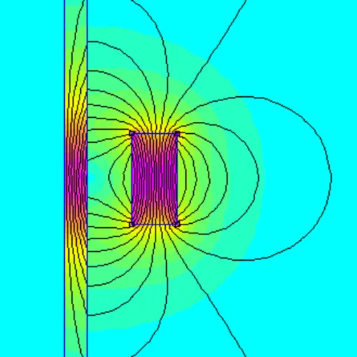
The physical meaning is straightforward. Every segment of a magnetic circuit, whether it is a steel core, an air gap, or a joint between two pieces of iron, resists the establishment of magnetic flux to some degree. The longer the flux path, the smaller the cross-sectional area, and the lower the magnetic permeability of the material, the greater the reluctance. High reluctance means you need more magnetomotive force (more ampere-turns in the coil) to push a given amount of flux through the circuit.
For a deeper understanding of how material permeability affects reluctance, see our guide on magnetic permeability and its role in electrical equipment performance.
The Magnetic Reluctance Formula
The standard formula for magnetic reluctance is:
R = l / (μ × A)
Where:
R is reluctance in H-1 (ampere-turns per weber)
l is the length of the magnetic path in meters
μ is the absolute permeability of the material in H/m
A is the cross-sectional area of the flux path in square meters
Absolute permeability (μ) equals the permeability of free space (μ₀ = 4π × 10-7 H/m) multiplied by the relative permeability (μᵣ) of the material. For non-magnetic materials like air, μᵣ equals 1. For electromagnetic pure iron grades like DT4C, μᵣ can exceed 10,000 under optimal conditions.
This formula reveals three design levers engineers can pull to control reluctance:
Path length (l): Shorter flux paths reduce reluctance proportionally. Compact core geometries with shorter magnetic paths deliver lower reluctance.
Cross-sectional area (A): Larger core cross-sections reduce reluctance. This is one reason designers increase core size when they need to handle higher flux densities.
Permeability (μ): Higher-permeability materials dramatically reduce reluctance. Because permeability appears in the denominator and can vary by orders of magnitude between materials, this is often the most powerful lever.
A quick calculation illustrates the impact. Consider a toroidal core with a mean path length of 0.3 m and a cross-sectional area of 0.001 m2. If the core material is DT4C pure iron with a relative permeability of 10,000, the reluctance works out to roughly 23,900 H-1. Replace that core with air (μᵣ = 1), and the reluctance jumps to approximately 239,000,000 H-1. The air path offers roughly ten thousand times more opposition to flux than the pure iron core. This enormous ratio explains why ferromagnetic cores are essential in every practical electromagnetic device.
Need help calculating reluctance for your specific magnetic circuit? Our engineering team can review your core geometry and operating conditions to recommend the optimal DT grade and dimensions. Contact us for a material consultation.
Why Air Gaps Dominate Magnetic Circuit Design
In practice, most magnetic circuits contain at least one air gap. Transformers have small gaps at lamination joints. Relays and solenoids have intentional gaps that define the armature stroke. Motors have a precisely controlled gap between rotor and stator. These air gaps introduce disproportionately high reluctance into the circuit because air has a relative permeability of essentially 1.
The contrast is dramatic. A 1 mm air gap in a circuit where the iron path is 300 mm long contributes more reluctance than the entire iron path if the iron has a relative permeability above 10,000. The air gap, despite being a tiny fraction of the total path length, can dominate the magnetic behavior of the entire circuit.
This fact has profound design implications. Engineers who focus exclusively on core material selection while ignoring air gap geometry may find that their high-permeability iron provides minimal benefit. Conversely, engineers who minimize and precisely control air gaps while using good core material achieve the lowest overall reluctance and the best device performance.
Air Gap Effects in Transformers
Transformer cores are built from stacked laminations or wound strips, and the joints between laminations introduce small air gaps. Even when laminations are tightly butted, the thin oxide layer and surface roughness create a microscopic gap that adds reluctance. Grain-oriented silicon steel laminations with step-lap joint designs minimize this effect by distributing the gap across multiple interfaces rather than concentrating it at a single joint.
For instrument transformers where accuracy depends on predictable magnetizing characteristics, even small variations in joint reluctance can introduce ratio errors. Manufacturers who assemble cores from precision-cut laminations with controlled surface finish achieve tighter electrical specifications than those using rough-cut stock.
Air Gap Effects in Relays and Solenoids
In relays and solenoids, the air gap is not an imperfection. It is a design parameter. The gap defines the stroke length and the force-versus-position characteristic of the actuator. When the armature is open, the gap is at maximum and the circuit reluctance is high. As the armature closes, the gap shrinks, reluctance drops, and the magnetic force increases rapidly.
This nonlinear relationship between gap distance and reluctance is why relay pull-in voltage differs significantly from drop-out voltage. At pull-in, the gap is large and the circuit needs high magnetomotive force to generate enough flux. Once the armature snaps closed, the much smaller gap requires far less magnetomotive force to maintain the closed state. Engineers who understand reluctance can optimize coil design to ensure reliable pull-in at minimum voltage while avoiding excessive holding current that wastes energy and generates heat.
A relay manufacturer in Wenzhou redesigned their DC relay by reducing the residual air gap from 0.08 mm to 0.03 mm through tighter machining tolerances on the armature stop. The change increased holding force by 30% without any modification to the coil or core material. The lower reluctance at the closed position allowed the coil to generate more flux with the same current, directly translating into stronger magnetic force.
Air Gap Effects in Motors
Motor designers face a constant tension between electromagnetic performance and mechanical clearance. A smaller air gap reduces reluctance and improves torque production, but it also demands tighter manufacturing tolerances and increases the risk of rotor-to-stator contact during operation. Most motor designs specify an air gap that balances electromagnetic efficiency against practical mechanical constraints.
For brushless DC motors and permanent magnet synchronous motors, the effective air gap includes the physical gap plus the thickness of the permanent magnets (since magnets have permeability close to 1). This effective gap can be several millimeters, which makes the choice of stator core material even more important. High-permeability pure iron in the stator helps compensate for the large effective reluctance introduced by the magnet gap.
How Material Selection Reduces Magnetic Reluctance
Since permeability appears in the denominator of the reluctance formula, selecting a material with high magnetic permeability is the most effective single step to reduce reluctance in the iron portions of a magnetic circuit. Not all ferromagnetic materials perform equally, and the differences have direct engineering and economic consequences.
Electromagnetic Pure Iron
Electromagnetic pure iron, particularly ultra-low carbon grades like DT4C, offers among the highest permeability values of any commercially available magnetic material. Initial relative permeability can exceed 10,000, with maximum values surpassing 100,000 under favorable conditions. This translates to extremely low reluctance per unit length of flux path.
The reason lies in chemical purity. Carbon, sulfur, phosphorus, and nitrogen atoms in the crystal lattice create pinning sites that obstruct magnetic domain wall motion. By controlling carbon content to 0.004% or below, DT4C grade pure iron minimizes these obstacles. Domain walls move freely, permeability climbs, and reluctance drops.
For DC and low-frequency applications, pure iron offers the best combination of low reluctance, high saturation induction, and reasonable cost. Relay cores, solenoid plungers, transformer yokes, and sensor elements all benefit from the low reluctance that pure iron delivers.
Our soft magnetic materials guide compares pure iron against other soft magnetic materials for engineers evaluating their options.
Silicon Steel
Silicon steel adds 1% to 4% silicon to iron, which increases electrical resistivity and reduces eddy current losses at power frequencies. The trade-off is lower permeability compared to pure iron. Grain-oriented silicon steel achieves relative permeability of 5,000 to 8,000 in the rolling direction, which is excellent but below what pure iron can deliver.
For large power transformers operating at 50 Hz or 60 Hz, silicon steel often represents the better system-level choice because eddy current losses dominate total core loss at these frequencies. The somewhat higher reluctance of silicon steel is offset by its dramatically lower eddy current losses. Our transformer core materials guide explores these trade-offs in detail for power equipment designers.
Nickel-Iron Alloys
Permalloy and related nickel-iron alloys achieve the highest permeability of any metallic material, with initial relative permeability exceeding 100,000. These alloys deliver extremely low reluctance per unit length. However, their high nickel content makes them expensive, and they saturate at lower flux densities than pure iron.
Nickel-iron alloys find use in magnetic shielding, precision current transformers, and specialized sensor applications where the extreme permeability justifies the cost. For general-purpose electromagnetic devices, pure iron provides adequate reluctance reduction at a fraction of the price.
Soft Ferrites
Soft ferrites are ceramic magnetic materials with permeability ranging from 1,000 to 15,000 depending on composition. Their very high resistivity makes them ideal for high-frequency applications above 100 kHz where metallic cores suffer excessive eddy current losses. However, ferrites saturate at much lower flux densities (typically 0.3 to 0.5 T) compared to pure iron (above 2.0 T), which limits their use in power applications.
For engineers working on switching power supplies, RF inductors, or EMI filters, ferrites offer the right balance of permeability and resistivity. For everything else operating below 10 kHz, metallic materials like pure iron deliver lower reluctance and higher saturation.
Want to see how DT4C pure iron compares to other materials for your specific reluctance requirements? Explore our full range of electromagnetic pure iron products to find the right grade and format for your application.
Calculating Magnetic Reluctance for Real Circuits
Most practical magnetic circuits contain multiple segments with different materials and cross-sections. The total reluctance is the sum of all segment reluctances in series, plus the parallel paths considered appropriately.
Example: Relay Magnetic Circuit
Consider a DC relay with the following flux path segments:
| Segment | Material | Length (mm) | Area (mm²) | μᵣ |
|---|---|---|---|---|
| Yoke | DT4C pure iron | 80 | 100 | 8,000 |
| Armature | DT4C pure iron | 30 | 100 | 8,000 |
| Working air gap | Air | 0.5 | 100 | 1 |
The reluctance of the yoke segment works out to approximately 796 H-1. The armature segment contributes roughly 298 H-1. But the tiny 0.5 mm air gap contributes 3,979,000 H-1. The air gap alone accounts for more than 99.97% of the total circuit reluctance.
This calculation demonstrates why air gap control is paramount in relay design. Even with excellent core material, the air gap dominates. However, using low-permeability material in the yoke and armature would make things even worse. If the yoke were made from a material with μᵣ of 1,000 instead of 8,000, the yoke reluctance would jump to 6,366 H-1. That increase is small in absolute terms compared to the air gap, but it still means the coil needs more ampere-turns to establish the same flux. Over thousands of relays in production, those extra ampere-turns translate to more copper, larger coils, and higher manufacturing costs.
Example: Transformer Core Circuit
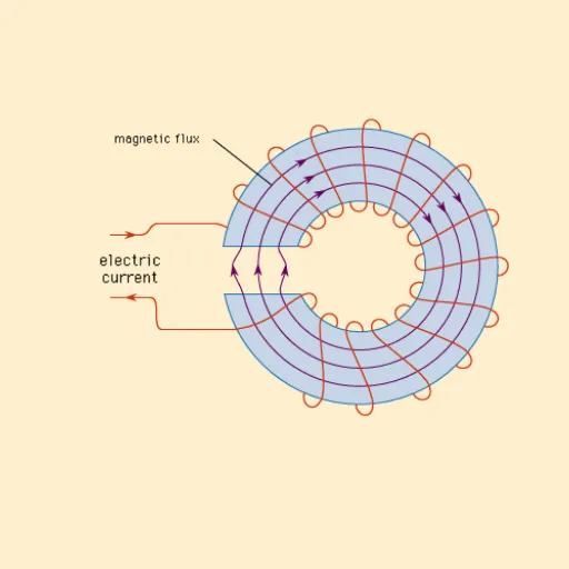
A toroidal transformer core made from DT4C cold-rolled pure iron sheet has a mean path length of 0.4 m, a cross-sectional area of 0.002 m2, and a relative permeability of 12,000. The reluctance of the iron path alone is approximately 13,263 H-1.
If the core is assembled from stacked laminations with four butt joints, each joint introduces an effective air gap of about 0.02 mm due to surface roughness and oxide layers. Four joints add 0.08 mm of effective air gap. The additional reluctance from these joints is approximately 318,000 H-1. That is roughly 24 times the reluctance of the entire iron path, all from joints that are nearly invisible to the naked eye.
This is why step-lap joint designs and precision-slit laminations matter. By distributing the air gap across a longer effective joint length and by ensuring clean, flat mating surfaces, manufacturers can reduce joint reluctance by an order of magnitude or more. Our guide to electromagnetic pure iron processing explains how precision slitting and surface preparation preserve the low-reluctance advantages of high-grade pure iron.
How Processing Affects Reluctance Through Permeability
The reluctance formula uses material permeability as a constant, but in reality, permeability depends heavily on processing history. This means that the same grade of pure iron can exhibit very different reluctance depending on what happens to it during manufacturing.
Cold working from stamping, bending, punching, or cutting introduces mechanical stress and crystal defects into the material. These defects pin magnetic domain walls and reduce permeability. A stamped relay core lamination that has not been annealed may exhibit permeability 40% to 60% below its annealed value. Since reluctance is inversely proportional to permeability, the effective reluctance of the stamped part could be two to three times higher than the material specification suggests.
Annealing reverses this damage. A hydrogen anneal at 800°C to 900°C recrystallizes the grain structure, relieves internal stress, and restores permeability to near-itsoretical values. Manufacturers who stamp or machine pure iron components and then anneal them achieve significantly lower reluctance in the finished part compared to those who skip the anneal.
The implications are practical and financial. If you purchase high-permeability DT4C pure iron but stamp it into laminations without annealing, you have paid for a premium material while getting the magnetic performance of a cheaper one. The reluctance of your core will be much higher than the material certificate suggests. Budgeting for post-processing annealing is not an optional extra. It is essential to realizing the low-reluctance potential of the raw material.
Our article on how cold drawing affects magnetic flux density in pure iron provides detailed data on how mechanical processing changes the magnetic properties that determine reluctance.
Looking for pure iron that maintains low reluctance through your production process? Our precision processing services include slitting, cutting, and surface preparation designed to preserve magnetic properties. Request a quote for your specific requirements.
Practical Strategies to Minimize Reluctance in Your Designs
Engineers designing electromagnetic devices can apply several practical strategies to reduce magnetic circuit reluctance and improve device performance.
Minimize Air Gap Length
Every fraction of a millimeter of air gap adds enormous reluctance to the circuit. Design tolerances and manufacturing processes should control air gaps to the minimum achievable without compromising mechanical function. For motors, this means tight bearing tolerances and precise rotor-stator alignment. For relays, it means machining armature stops to precise dimensions. For transformer cores, it means using step-lap joints and controlling lamination flatness.
Maximize Cross-Sectional Area
Larger core cross-sections reduce reluctance proportionally. When space and weight constraints allow, increasing the core cross-section is a straightforward way to lower reluctance. This approach also reduces flux density in the core, which can push the operating point deeper into the high-permeability region of the B-H curve and further reduce reluctance.
Choose High-Permeability Core Materials
As the calculations above demonstrate, material permeability has an enormous effect on reluctance. For DC and low-frequency applications, DT4C electromagnetic pure iron provides the highest readily available permeability at reasonable cost. For power frequency applications where eddy losses are a concern, grain-oriented silicon steel offers a good compromise. Match the material to your operating frequency and flux density requirements.
Anneal After Mechanical Processing
Any cold working step, including stamping, cutting, bending, and machining, degrades permeability and increases effective reluctance. A proper hydrogen anneal after processing restores the material's magnetic properties. Include annealing in your production process flow and verify the results with permeability measurements on representative samples.
Control Surface Quality and Joint Interfaces
Oxide layers, burrs, and surface roughness at lamination joints introduce effective air gaps that increase reluctance. Precision slitting with clean, deburred edges minimizes this effect. Proper storage to prevent oxidation before assembly also helps. For critical applications, specify surface roughness requirements on your material purchase orders.
Avoid Magnetic Saturation
When a magnetic material approaches saturation, its effective permeability drops dramatically. A core operating near saturation has much higher reluctance than the same core at moderate flux densities. Design the core cross-section to keep peak flux density well below the saturation limit of the material, accounting for transient overloads and inrush conditions. DT4C pure iron saturates at approximately 2.1 T, which provides generous headroom for most applications.
A stator core manufacturer in Dongguan applied these principles when redesigning a servo motor for higher power density. By switching to DT4C pure iron laminations, reducing the air gap from 0.8 mm to 0.5 mm through tighter housing tolerances, increasing the core cross-section by 15%, and adding a hydrogen anneal after stamping, they achieved a 26% increase in torque density without increasing the motor's external dimensions. The reluctance of the magnetic circuit dropped by more than 40% compared to the previous design.
Conclusion
Magnetic reluctance is the invisible gatekeeper of every electromagnetic device. It determines how much current your coil needs, how much heat your core generates, and how efficiently your design converts electrical energy into useful magnetic work. While the concept is straightforward, the design levers that control reluctance span material selection, geometric precision, processing discipline, and operating point management.
Key takeaways from this guide:
Magnetic reluctance is inversely proportional to permeability and cross-sectional area, and directly proportional to flux path length.
Air gaps, even tiny ones, typically dominate the total reluctance of practical magnetic circuits.
High-permeability materials like DT4C electromagnetic pure iron minimize reluctance in the ferromagnetic portions of the circuit.
Mechanical processing degrades permeability unless followed by proper annealing, effectively increasing reluctance in finished parts.
A systematic approach to reluctance management, covering material, geometry, processing, and operating conditions, delivers measurable improvements in device efficiency, size, and cost.
The engineers who get magnetic reluctance right are the ones who build smaller, cooler, more efficient electromagnetic devices. The ones who ignore it end up like the Shandong motor team, burning weeks of engineering time chasing symptoms instead of addressing the root cause.
Ready to reduce reluctance in your magnetic circuits with precision-engineered pure iron? Contact Shanxi Jurun Technology Co., Ltd. today for a custom quote on DT4C electromagnetic pure iron in coils, sheets, bars, or custom-cut formats tailored to your exact specifications.
Recently Posted
-
Transformer Calculation: A Practical Guide for Core Design and Material Selection
June 30, 2026A 2-millimeter error in core cross-section can quietly drain thousands of dollars from a transformer production run. That is exact Read More
 -
Magnetic Flux: A Complete Guide for Electrical Engineering Applications
June 30, 2026In late 2024, a power equipment manufacturer in Poland received a shipment of transformer cores that looked perfect on paper. The Read More
 -
Magnetic Field Strength: A Practical Guide for Electromagnetic Design
June 30, 2026When Wang Chen's solenoid valve line began missing stroke targets in March 2026, his team suspected the usual suspects: worn s Read More
 -
AC Electromagnet: Design, Applications, and Material Selection Guide
June 30, 2026Last quarter, a relay manufacturer in Dongguan shipped 5,000 solenoid valves to a European automotive client. Two weeks after inst Read More

Contact Us
Recommended Products
-
 Seamless Tube With Good Cold Electrical Pure Iron Fittings Hot Workability for Forming Fittings and ConduitsNegotiableMOQ: 1 Ton
 -
Electromagnetic Pure Iron Forging for Automotive Sensor ManufacturingNegotiableMOQ: 100 Kilograms
-
Precision Cut Pure Iron Square Bar High Saturation Induction Raw Material for Generator and RotorNegotiableMOQ: 100 Kilograms
-
DT4C Super Grade Electromagnetic Pure Iron Bright Bar With Bundle Weight 30-100kg for Easy TransportationNegotiableMOQ: 1 Ton
-
DT4C Electromagnetic Pure Iron Cold-Drawn Wire 0.5mm-6.0mm Diameter for TransformersNegotiableMOQ: 100 Kilograms
-
Industrial Pure Iron Bar for Electromagnetic Relay and Sensor ProductionNegotiableMOQ: 1 Ton
-
Electromagnetic Pure Iron Thin Sheet 0.3mm-0.8mm for Solenoid and Relay ManufacturingNegotiableMOQ: 500 Kilograms
-
Electrical Pure Iron Hot-Rolled Coil for Magnetic Components With Low Iron LossNegotiableMOQ: 1 Ton
-
Low Carbon DT4C Pure Iron Round Bar With 99.8% Fe Content for Electrical ApplicationsNegotiableMOQ: 1 Ton
-
Cold Rolled Pure Iron Slit Coil DT4C Grade Ultra Low Carbon ≤0.004% for Magnetic ComponentsNegotiableMOQ: 1 Ton
-
Low Iron Loss Electromagnetic Pure Iron Hot-Rolled Coil DT4C for Transformer CoresNegotiableMOQ: 1 Ton
-
Soft Magnetic Pure Iron Sheet With Minimum Iron Loss for High-Efficiency MotorsNegotiableMOQ: 1 Ton
-
Electromagnetic Pure Iron Cold Rolled Coil DT4C for High Magnetic Permeability ApplicationsNegotiableMOQ: 1 Ton
-
Industrial Pure Iron Tube Superior Surface Quality Electromagnetic Pure Iron Tube for Welding and Plating ProcessesNegotiableMOQ: 1 Ton
-
DT4 Seamless Pure Iron Tubing for High-Performance Electrical Equipment ApplicationsNegotiableMOQ: 1 Ton
-
DT4C Iron Wire Rod for Precision Magnetic Shielding ApplicationsNegotiableMOQ: 100 Kilograms
-
Industrial Pure Iron Fittings DT4 Pure Iron Seamless Tube With Low Hysteresis Loss for Electromagnetic SystemsNegotiableMOQ: 1 Ton
-
DT4C Cold Rolled Coil Slitting for Electrical Enclosure ManufacturingNegotiableMOQ: 1 Ton
-
Anti Rust Coated Pure Iron Square Bar Low Carbon Raw Material for Welding and Forging Magnetic PartsNegotiableMOQ: 100 Kilograms
-
DT4 Pure Iron Cold-Drawn Wire 0.5mm-6.0mm Diameter for Precision EngineeringNegotiableMOQ: 500 Kilograms