
 Business License

Magnetic Saturation in Pure Iron: A Practical Engineering Guide
Chen Wei still remembers the Monday morning his transformer test bench started throwing anomalies. A new batch of 50 kVA distribution transformers was passing routine tests until the inrush current simulation. At 1.8 teslas peak flux density, the cores screamed audibly. Current draw spiked 340% above design value. Winding temperatures climbed past safe limits in under three minutes. The problem was not faulty windings or bad insulation. The core steel had hit magnetic saturation at a flux density the design assumed it could handle. Switching to electromagnetic pure iron with higher saturation induction solved the issue, but the delay cost his factory two weeks of delivery schedule.
Chen's experience is not unusual. Magnetic saturation represents one of the most destructive and least understood failure modes in electromagnetic equipment. Engineers who design transformers, motors, and relays without accounting for saturation limits risk exactly the kind of catastrophic performance collapse Chen encountered.
You already know that core material selection matters. This guide explains what magnetic saturation means in physical terms, why it limits your designs, how different materials behave as they approach saturation, and how to specify pure iron grades that keep your equipment operating safely below the saturation threshold.
What Magnetic Saturation Means for Core Materials
Magnetic saturation occurs when a ferromagnetic material can no longer increase its magnetization in response to stronger applied magnetic fields. At low and moderate field strengths, magnetic domains inside the material align with the external field. This alignment produces the high magnetic permeability that makes iron so valuable in electrical applications. As field strength increases, more domains rotate into alignment. Eventually, nearly all domains point in the same direction. Beyond this point, increasing the applied field produces almost no additional magnetization. The material has reached saturation.
Saturation flux density, also called saturation induction, measures the maximum magnetic flux density a material can sustain. For high-grade electromagnetic pure iron, this value reaches approximately 2.15 teslas. Silicon steel saturates around 2.0 teslas. Nickel-iron alloys saturate lower, typically between 0.7 and 1.6 teslas depending on composition. These numbers appear on material data sheets, but their practical meaning only becomes clear when you understand how close your design operates to these limits.
The distinction between magnetic permeability and magnetic saturation matters here. Permeability describes how easily a material reaches a given flux density. Saturation describes the absolute ceiling beyond which the material cannot go. A material with extremely high permeability might reach half its saturation value with minimal applied field. That efficiency is wonderful until a transient current pushes flux density toward the saturation limit. At that point, permeability collapses. The core behaves almost like air. Magnetizing current soars, copper losses multiply, and the device either fails or operates far outside its safe envelope.
Want to understand how magnetic permeability works hand-in-hand with saturation limits? Read our complete guide to magnetic permeability in pure iron.
Why Saturation Induction Sets the Hard Limit
Saturation induction is not a soft recommendation. It is a physical boundary imposed by atomic structure. In pure iron, saturation corresponds to the point where all magnetic moments in the crystal lattice align with the applied field. No known processing technique can push pure iron past roughly 2.15 teslas at room temperature. This makes saturation induction one of the few truly non-negotiable parameters in electromagnetic design.
The consequences of hitting magnetic saturation depend on the application, but they are never desirable. In a transformer, saturation causes magnetizing current to spike because the core can no longer support the flux demanded by the applied voltage. The excess current flows through the windings as heat. Core losses jump. Audible noise increases dramatically as the saturated regions vibrate at twice the operating frequency. Protection relays may trip. In extreme cases, insulation damage follows thermal runaway.
In motors and generators, saturation limits torque production and voltage regulation. As the field approaches saturation, additional field current yields diminishing returns. Efficiency drops. The machine may fail to deliver rated output during overload conditions. Permanent magnet machines face similar constraints when stator currents push the iron into saturation.
For relays and solenoids, saturation means the armature stops developing additional force just when the application needs it most. A solenoid designed with inadequate saturation margin may fail to pull in under low voltage conditions or high mechanical load. Once saturated, the only way to generate more force is to increase physical size, which defeats the purpose of compact electromagnetic design.
How Purity and Grade Affect Saturation Behavior
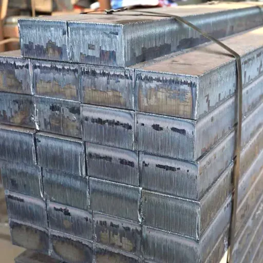
Not all pure iron grades offer identical saturation characteristics. While saturation induction is primarily an intrinsic property of the iron crystal itself, impurities and processing history influence the practical saturation behavior you see in finished components.
Carbon content plays the most critical role. High carbon levels form iron carbide precipitates that distort the crystal lattice. These distortions do not change the theoretical saturation value much, but they create local regions that saturate earlier than the surrounding matrix. The result is a softer saturation knee and earlier onset of nonlinear behavior. Ultra-low carbon grades like DT4C, with carbon content at or below 0.004%, maintain the sharpest saturation transition and the highest effective saturation induction.
Our DT4C pure iron specifications detail the exact chemical composition and magnetic properties that make this grade the preferred choice for high-flux applications.
Silicon and aluminum additions, common in electrical steels, reduce saturation induction slightly while increasing resistivity. The trade-off favors silicon steel in power frequency transformers where eddy current losses matter more than peak flux capability. For applications requiring maximum flux density, such as high-power pulse transformers or compact solenoids, unalloyed pure iron delivers superior saturation performance.
Processing history also matters. Cold working introduces dislocations and residual stress that degrade magnetic properties. A cold-drawn pure iron bar may exhibit measurably lower permeability and a less favorable saturation curve than annealed material. Our article on the impact of cold drawing on magnetic flux density in pure iron explains how drawing processes affect the B-H curve and what you can do to restore performance through heat treatment.
Grain size and orientation influence how sharply saturation occurs. Large, well-oriented grains support higher permeability and a more abrupt saturation knee. Small, randomly oriented grains produce gradual saturation and higher hysteresis loss. This is why annealing after stamping or cutting is almost mandatory for components that must operate near their saturation limit.
Magnetic Saturation in Real-World Applications
Understanding saturation in theory is useful only if you can apply it to actual equipment. Three application categories show how saturation limits drive material selection and design margins.
Power Transformers and Inductors
Transformer designers live in constant tension between core size and saturation margin. Higher flux density means smaller cores, less copper, and lower material cost. Push too close to saturation, and you invite the exact failure Chen Wei experienced.
Distribution transformers typically operate with peak flux density around 1.6 to 1.7 teslas at rated voltage. This leaves approximately 0.4 to 0.5 teslas of headroom against saturation. That headroom absorbs voltage transients, harmonic content, and the DC offset that occurs during inrush. A transformer designed with 1.9 teslas nominal peak flux has almost no margin. Any disturbance pushes it into saturation.
High-frequency inductors face even tighter constraints. At switching frequencies above 20 kHz, core loss often limits operating flux density well below saturation. Ferrite cores, common in these applications, saturate around 0.3 to 0.5 teslas. Engineers must verify that peak flux during worst-case transients stays safely below this limit. Pure iron and iron-based amorphous alloys offer higher saturation but higher loss at these frequencies, creating material selection trade-offs that depend on the specific operating envelope.
Electromagnetic Relays and Solenoids
Relay engineers rarely think about saturation until a pull-in failure forces them to. A solenoid armature generates force proportional to the square of flux density. As the armature approaches the pole face, flux density rises sharply. If the core material saturates before the armature seats, force development stalls. The solenoid may chatter, overheat, or fail to hold against spring pressure.
A relay manufacturer in Zhejiang discovered this problem during qualification of a new automotive relay line. The original core material, a standard low-carbon steel, saturated at 1.9 teslas. During cold-temperature testing at minus 40 degrees Celsius, coil resistance dropped and current rose. The resulting flux density pushed the core into saturation. Pull force dropped 18% below specification. After switching to DT4C electromagnetic pure iron with saturation induction above 2.1 teslas, the relay passed all qualification tests with margin to spare. The material cost increase was minor compared to the cost of a redesign.
For precision relay and solenoid applications, pure iron cores offer predictable force curves and consistent saturation characteristics. Variability in saturation behavior between material lots causes more field failures than almost any other parameter except permeability drift.
Electric Motors and Generators
Electric machines rely on magnetic circuits that must remain unsaturated across the full operating range. Saturation in the stator teeth reduces slot area effectiveness. Saturation in the rotor limits field excitation. Either condition reduces output torque, degrades efficiency, and increases losses.
When a Jiangsu motor manufacturer developed a compact high-torque servo motor, they initially used silicon steel laminations with saturation induction near 2.0 teslas. During peak torque testing, localized tooth saturation caused torque ripple and audible noise. Switching to pure iron laminations raised the effective saturation ceiling and smoothed torque production. The motor met its performance target without increasing frame size.
Permanent magnet synchronous motors face a related challenge. The permanent magnet field biases the operating point on the B-H curve. Stator current must work against this bias without pushing local iron regions into saturation. High-saturation iron provides more design freedom for flux weakening and field-oriented control strategies.
Measuring Saturation Flux Density Accurately
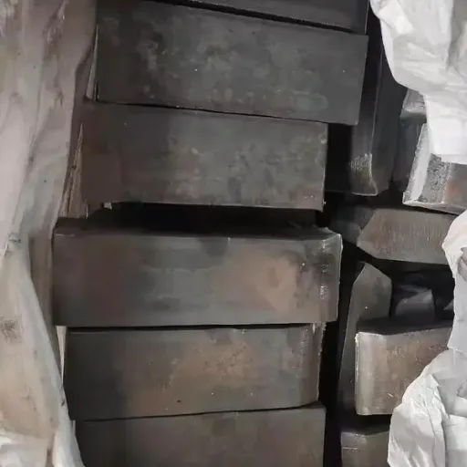
Material data sheets list saturation values, but engineers should understand how these numbers are determined and what they mean for finished components.
Standard measurement uses a toroidal sample with uniform cross-section. Primary and secondary windings encircle the toroid. The primary winding applies a controlled magnetizing force. The secondary winding measures flux change through induced voltage. Integrating this voltage yields flux density. Plotting flux density against applied field strength produces the familiar B-H curve. Saturation induction is read from the flat portion of this curve at high field strength.
The test assumes uniform material, uniform flux distribution, and negligible air gaps. Real components violate all three assumptions. Stacked laminations have interlaminar gaps. Cut edges create local stress. Bolt holes and slots distort flux paths. The effective saturation behavior in a finished transformer core differs from the toroidal sample that generated the certificate.
Temperature effects are modest for saturation induction compared to permeability, but they exist. Saturation induction decreases slightly as temperature rises. For most room-temperature applications, this drift is negligible. For devices operating above 100 degrees Celsius, designers should consult temperature-corrected data.
Incoming inspection for saturation characteristics is uncommon because the test requires specialized equipment. Most manufacturers rely on grade certification and supplier reputation. For critical applications, a simple ring-sample test or comparison of B-H curves between lots provides assurance that material behavior has not drifted.
Need pure iron that meets guaranteed saturation specifications for your transformers or solenoids? Contact our engineering team to review test data and request material certifications for DT4C pure iron.
Choosing Materials That Stay Below the Saturation Line
Selecting core material based on saturation induction alone oversimplifies the problem. A structured approach balances saturation against permeability, resistivity, cost, and processing requirements.
First, calculate your peak flux density under all operating conditions, not just nominal load. Include inrush transients, voltage swells, harmonic content, and worst-case temperature extremes. Your design should keep peak flux at least 10% below the material's saturation induction at operating temperature. Critical applications may demand 15% to 20% margin.
Second, match the material to your frequency. DC and low-frequency applications favor pure iron because its high saturation induction provides maximum flux capability. At 50 Hz or 60 Hz, silicon steel may win on total loss despite lower saturation. Above 1 kHz, ferrites or amorphous alloys may be necessary even though their saturation limits are lower. The best material is the one that satisfies all constraints simultaneously, not the one that excels in a single parameter.
Third, account for processing effects. Stamping, cutting, and bending reduce effective permeability and can soften the saturation knee. If your manufacturing process involves significant cold work, budget for stress-relief annealing or specify pre-annealed material. Our guide to soft magnetic materials explains how heat treatment restores magnetic properties after forming operations.
Fourth, verify supplier consistency. Saturation induction varies little within a given grade of pure iron, but subtle differences in carbon content, grain structure, and inclusion levels affect the shape of the B-H curve near saturation. Reputable suppliers provide material certificates with measured B-H data, not just nominal grade claims. For high-volume production, incoming magnetic testing protects against the kind of lot-to-lot variation that causes unexplained field failures.
Fifth, consider total system cost, not just material cost per kilogram. Higher saturation induction can enable smaller cores, less copper, and lighter assemblies. The motor manufacturer in Jiangsu found that pure iron laminations cost more per kilogram than silicon steel, but the reduced frame size and copper savings offset the material premium. Saturation margin is not an expense. It is an investment in reliability and design flexibility.
Conclusion
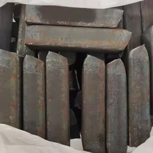
Magnetic saturation sits at the boundary between controlled operation and catastrophic failure in every electromagnetic device. The saturation induction of your core material sets a hard physical limit that no amount of design cleverness can exceed. Understanding where this limit lies, how close your design operates to it, and how material selection and processing affect the practical saturation behavior is essential for reliable equipment.
High-saturation pure iron remains the material of choice for applications demanding maximum flux density at low and moderate frequencies. Grades like DT4C deliver saturation induction above 2.1 teslas together with the ultra-low carbon content that preserves sharp saturation transitions and minimal hysteresis loss. For transformer manufacturers, relay engineers, and motor designers, this combination of high saturation, high permeability, and economical pricing keeps pure iron competitive against more exotic alloys.
Key takeaways to apply in your next design:
Calculate peak flux density under all transient and overload conditions, not just steady state
Maintain at least 10% margin between peak flux and material saturation induction
Account for processing effects when specifying raw material versus finished laminations
Request measured B-H curves on material certifications, not just grade names
Consider annealing requirements if your process involves cutting, stamping, or forming
Test incoming material lots if saturation consistency is critical to product performance
The next time you specify core material for a transformer, relay, or motor, remember Chen Wei's Monday morning surprise. A few minutes spent verifying saturation margins during design can save weeks of debugging, prevent field failures, and protect your reputation for reliable equipment.
Recently Posted
-
GB/T 6983 Electromagnetic Pure Iron Standard: Key Chemical and Magnetic Requirements
September 4, 2026A quality manager at an Indian relay manufacturer once received a mill test certificate from a Chinese supplier showing "DT4& Read More
 -
Pure Iron for Solenoid Valve Cores: Fast Response, Low Remanence, and Material Selection
September 4, 2026Some time ago, a pneumatic equipment manufacturer in Zhejiang began receiving customer complaints about solenoid valves that faile Read More
 -
How to Source Electromagnetic Pure Iron from China: A Step-by-Step Buyer's Guide
September 3, 2026Not long ago, a European automation company sent the same inquiry to six Chinese suppliers: "Need electromagnetic pure iron, Read More
 -
DT4 vs. DT4C Pure Iron: Magnetic Performance, Cost Differences, and When to Upgrade
September 3, 2026A solenoid valve producer in Jiangsu ordered DT4 cold-drawn bar for a new proportional valve line, reasoning that the grade was &q Read More

Contact Us
Recommended Products
-
 Seamless Tube With Good Cold Electrical Pure Iron Fittings Hot Workability for Forming Fittings and ConduitsNegotiableMOQ: 1 Ton
 -
Electromagnetic Pure Iron Forging for Automotive Sensor ManufacturingNegotiableMOQ: 100 Kilograms
-
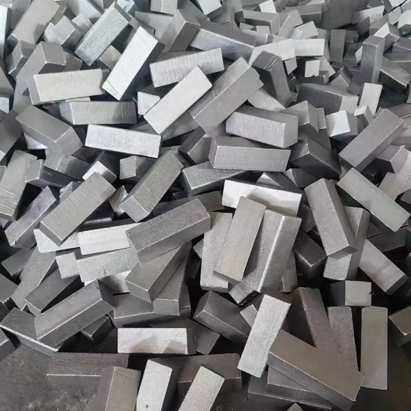
Precision Cut Pure Iron Square Bar High Saturation Induction Raw Material for Generator and RotorNegotiableMOQ: 100 Kilograms
-
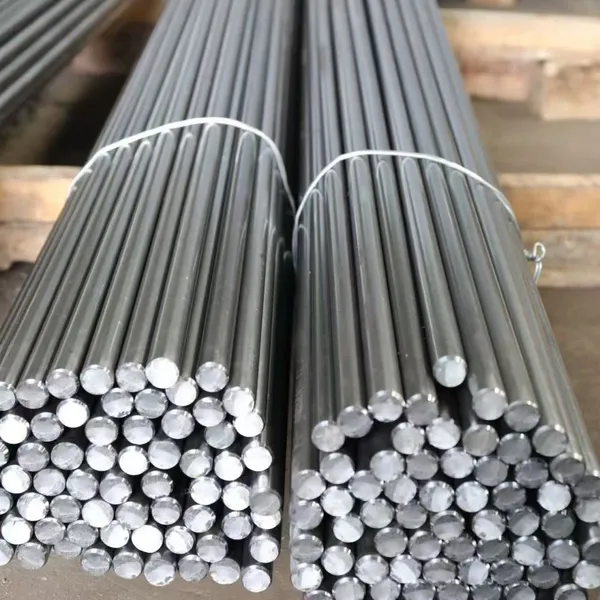
DT4C Super Grade Electromagnetic Pure Iron Bright Bar With Bundle Weight 30-100kg for Easy TransportationNegotiableMOQ: 1 Ton
-
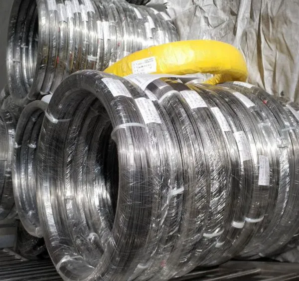
DT4C Electromagnetic Pure Iron Cold-Drawn Wire 0.5mm-6.0mm Diameter for TransformersNegotiableMOQ: 100 Kilograms
-
Industrial Pure Iron Bar for Electromagnetic Relay and Sensor ProductionNegotiableMOQ: 1 Ton
-
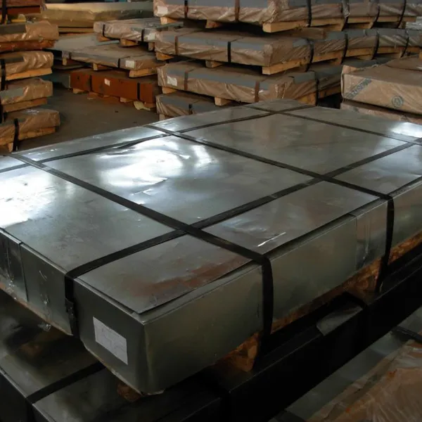
Electromagnetic Pure Iron Thin Sheet 0.3mm-0.8mm for Solenoid and Relay ManufacturingNegotiableMOQ: 500 Kilograms
-
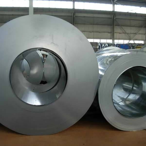
Electrical Pure Iron Hot-Rolled Coil for Magnetic Components With Low Iron LossNegotiableMOQ: 1 Ton
-
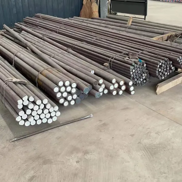
Low Carbon DT4C Pure Iron Round Bar With 99.8% Fe Content for Electrical ApplicationsNegotiableMOQ: 1 Ton
-
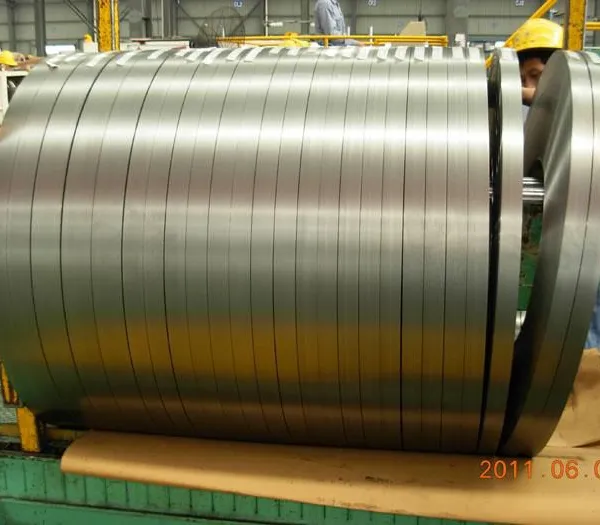
Cold Rolled Pure Iron Slit Coil DT4C Grade Ultra Low Carbon ≤0.004% for Magnetic ComponentsNegotiableMOQ: 1 Ton
-
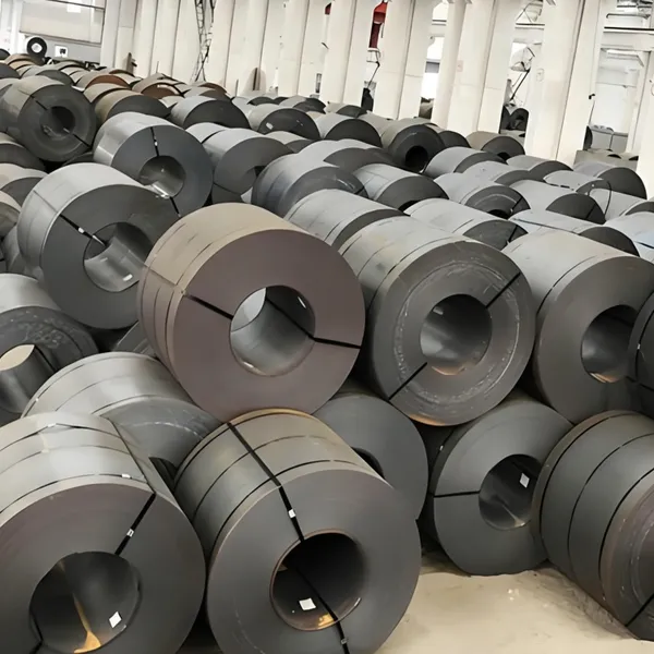
Low Iron Loss Electromagnetic Pure Iron Hot-Rolled Coil DT4C for Transformer CoresNegotiableMOQ: 1 Ton
-
Soft Magnetic Pure Iron Sheet With Minimum Iron Loss for High-Efficiency MotorsNegotiableMOQ: 1 Ton
-
Electromagnetic Pure Iron Cold Rolled Coil DT4C for High Magnetic Permeability ApplicationsNegotiableMOQ: 1 Ton
-
Industrial Pure Iron Tube Superior Surface Quality Electromagnetic Pure Iron Tube for Welding and Plating ProcessesNegotiableMOQ: 1 Ton
-
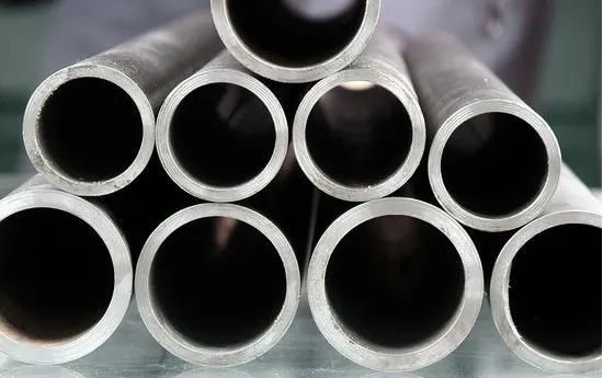
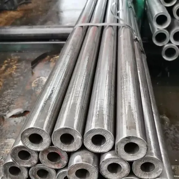
DT4 Seamless Pure Iron Tubing for High-Performance Electrical Equipment ApplicationsNegotiableMOQ: 1 Ton
-
DT4C Iron Wire Rod for Precision Magnetic Shielding ApplicationsNegotiableMOQ: 100 Kilograms
-
Industrial Pure Iron Fittings DT4 Pure Iron Seamless Tube With Low Hysteresis Loss for Electromagnetic SystemsNegotiableMOQ: 1 Ton
-
DT4C Cold Rolled Coil Slitting for Electrical Enclosure ManufacturingNegotiableMOQ: 1 Ton
-
Anti Rust Coated Pure Iron Square Bar Low Carbon Raw Material for Welding and Forging Magnetic PartsNegotiableMOQ: 100 Kilograms
-
DT4 Pure Iron Cold-Drawn Wire 0.5mm-6.0mm Diameter for Precision EngineeringNegotiableMOQ: 500 Kilograms