Motor Lamination Material: A Complete Guide to Better Motor Performance
What if the biggest drain on your motor's efficiency isn't the winding design, the cooling system, or the control electronics, but the thin sheets stacked inside the core? Motor lamination material quietly determines how much energy becomes useful torque and how much dissipates as heat. For manufacturers chasing tighter efficiency regulations and longer product life, that choice matters more than ever.
You already know that core losses can consume 15% to 25% of a motor's input energy. You also know that switching to a better lamination steel can shrink those losses, reduce operating temperature, and cut lifetime costs. In this guide, you'll learn what motor lamination material really is, how it affects performance, which options fit different applications, and how to select the right grade for your next design. We'll also look at processing methods, coatings, and the trends shaping next-generation motors.
When Lian Wei, an EV motor engineer in Suzhou, first prototyped a high-efficiency drive motor in early 2024, she specified a standard silicon steel without reviewing core-loss grades. During dynamometer testing, the motor ran 8°C hotter than expected and fell 2% short of its efficiency target. After switching to a thinner, lower-loss electrical steel, her team recovered the full efficiency gap and reduced cooling-system costs by 12%. The lamination material alone changed the project's economics.
Need pure iron laminations for precision motor cores? Explore our DT4C electromagnetic pure iron materials →
What Is Motor Lamination Material?
Motor lamination material is the specially formulated metal used to stamp the thin, stacked sheets that form a motor's stator and rotor cores. Instead of machining cores from solid blocks, manufacturers punch thousands of individual laminations from thin sheet stock and stack them into a solid-looking core. Each sheet is electrically insulated from its neighbors, which breaks the paths for eddy currents and keeps the core from overheating.
The most common motor lamination materials are electrical steels, also called lamination steel or transformer steel. These alloys are engineered to combine high magnetic permeability with low core loss. Small amounts of silicon are added to iron to increase electrical resistivity, which suppresses eddy-current losses at higher frequencies. Pure iron and specialty alloys such as nickel-iron are also used when maximum permeability or specific magnetic properties are required.
Choosing the right motor lamination material starts with understanding the trade-off between magnetic performance, mechanical strength, processability, and cost. A high-silicon electrical steel may deliver excellent efficiency, but it can be harder to punch and more brittle than lower-silicon alternatives. A pure iron grade such as DT4C offers outstanding magnetic permeability and ultra-low carbon content, making it ideal for high-performance electromagnetic components where every fraction of a percent counts.
Why Motor Lamination Material Directly Affects Motor Efficiency
Every time a motor operates, its core material travels through a repeating magnetic cycle. Two types of loss occur during that cycle. Hysteresis loss is the energy consumed as magnetic domains realign with each change in field direction. Eddy-current loss is the energy dissipated as circulating currents induced within the conductive core by the changing magnetic field. Together, these core losses determine how much extra energy a motor draws and how much heat it generates.
Motor lamination material attacks both loss mechanisms. Alloying iron with silicon raises electrical resistivity, which reduces eddy-current magnitude. Thinner gauge sheets further limit eddy-current paths because the currents cannot build large loops across a thin cross-section. Better grain orientation and annealing reduce hysteresis loss by making domain wall movement easier. The result is a cooler, more efficient motor that can deliver the same output with less input power.
At a precision-machining shop in Ningbo, production manager Zhang Hao noticed that one of his relay-motor lines was producing 6% more scrap than the others. The culprit was inconsistent hardness in the standard steel laminations, which dulled punches faster and created burrs that shorted adjacent laminations. Switching to a consistent, low-carbon pure iron grade cut punch wear by nearly half and brought scrap rates back in line. Material consistency turned out to be as important as the grade itself.
High-efficiency motors used in electric vehicles, industrial drives, and premium appliances depend on thin-gauge, low-loss laminations. As global efficiency standards tighten, the pressure to optimize motor lamination material is moving from the engineering margins to the center of product design.
Common Types of Motor Lamination Material
Manufacturers can choose from several families of motor lamination material, each suited to different performance targets and budgets. Understanding the differences helps you match the material to the application rather than defaulting to the cheapest option.
Non-Oriented Electrical Steel
Non-oriented electrical steel has magnetic properties that are nearly uniform in every direction across the sheet. This makes it the default choice for rotating machines where the magnetic field rotates and never aligns with a single direction. Grades are classified by core loss, with designations such as M19, M27, M36, and M43 indicating progressively higher loss but lower cost.
Lower-loss grades use thinner sheets and tighter chemistry control. They cost more per kilogram, but the efficiency gains often repay the premium over the motor's lifetime. Most industrial motors, HVAC compressors, and standard pumps use non-oriented electrical steel because it balances performance, cost, and manufacturability.
Grain-Oriented Electrical Steel
Grain-oriented electrical steel has its crystal grains aligned so that magnetic flux flows most easily along the rolling direction. This alignment produces very low core loss in one direction, which is why grain-oriented steel dominates transformer cores. In motors, it is used only in specialized designs where the flux path is strongly directional and the manufacturing process can accommodate the anisotropy.
Silicon Steel Laminations
Silicon steel is the broad category that includes most electrical steels used in motors. Silicon content typically ranges from 0.5% to 6.5%. Higher silicon increases resistivity and reduces eddy-current loss, but it also makes the steel harder and more brittle. For general-purpose motors, 1% to 3% silicon is common. For high-efficiency or high-frequency motors, grades with 4% to 6.5% silicon deliver lower losses but require more careful handling.
Electromagnetic Pure Iron
Electromagnetic pure iron, including grades such as DT4C pure iron, offers extremely high magnetic permeability and very low coercive force. With carbon content at or below 0.004%, it minimizes hysteresis loss and provides stable magnetic behavior. Pure iron motor cores are common in precision relays, high-performance sensors, specialty motors, and research equipment where linear magnetic response matters.
Pure iron is softer and easier to machine than silicon steel, but it has lower resistivity, so eddy-current control depends heavily on lamination thickness and insulation. When paired with thin sheets and proper coatings, electromagnetic pure iron can outperform silicon steels in specific low-frequency or high-permeability applications.
Nickel-Iron and Cobalt-Iron Alloys
For extreme applications, nickel-iron alloys such as Permalloy and cobalt-iron alloys offer the highest permeability and lowest losses. These materials are expensive and typically reserved for aerospace, medical devices, precision instrumentation, and high-frequency power electronics where cost is secondary to performance.
Not sure which grade suits your motor design? Contact our engineering team for a tailored recommendation →
How to Choose the Right Motor Lamination Material
Selecting motor lamination material is not a one-size-fits-all decision. The best grade depends on motor topology, operating conditions, efficiency targets, production volume, and total cost of ownership. Use the following criteria to narrow the field.
Match the Material to Operating Frequency
Eddy-current losses increase with frequency, so high-speed motors and inverter-driven machines benefit from thinner laminations and higher-resistivity silicon steels. At line frequency, standard 0.50 mm or 0.35 mm non-oriented steel may be sufficient. For motors operating above a few hundred hertz, 0.25 mm, 0.20 mm, or even thinner gauges become worthwhile.
Balance Efficiency Targets with Cost
Premium electrical steels can improve efficiency by one or two percentage points, which sounds small but translates into significant energy savings over years of operation. Calculate the payback period using your expected duty cycle and electricity cost. For continuous-duty industrial motors, the premium often pays for itself quickly. For intermittent or low-cost appliances, a mid-grade steel may be the smarter choice.
Consider Mechanical and Processing Requirements
Some high-silicon steels are more brittle and produce more punch wear, which increases tooling cost and reduces dimensional accuracy. Pure iron grades such as DT4C are softer and easier to stamp, turn, and mill, making them attractive for complex shapes and short production runs. If your design requires extensive post-stamping machining, factor machinability into the material selection.
Verify Magnetic Directionality
Rotating machines generally need non-oriented steel because the magnetic field rotates. If your design has a strongly directional flux path, grain-oriented steel may offer lower loss, but only if the lamination geometry can respect the rolling direction. Using grain-oriented steel in the wrong orientation can actually increase losses.
Evaluate Supply Chain and Consistency
Even the best material specification fails if deliveries are inconsistent. Work with suppliers who can guarantee chemistry, thickness, and coating uniformity from lot to lot. Variability in hardness or insulation quality can increase scrap, shorten tool life, and degrade motor performance.
Procurement manager Sarah Chen had spent months qualifying a new motor lamination supplier for a European appliance contract. The initial samples met all specifications, but production lots began drifting in thickness by 0.02 mm. That tiny variation raised core losses enough to push the finished motor outside the customer's efficiency band. After switching to a supplier with in-house slitting and rigorous lot testing, Sarah eliminated the drift and protected the contract. Consistent supply can be as critical as the alloy itself.
Processing Methods and Coatings for Motor Laminations
Raw sheet steel rarely goes straight into a motor. It passes through several processing steps that influence final performance and manufacturability.
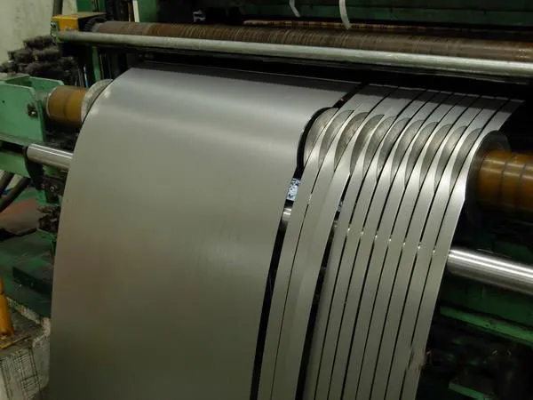
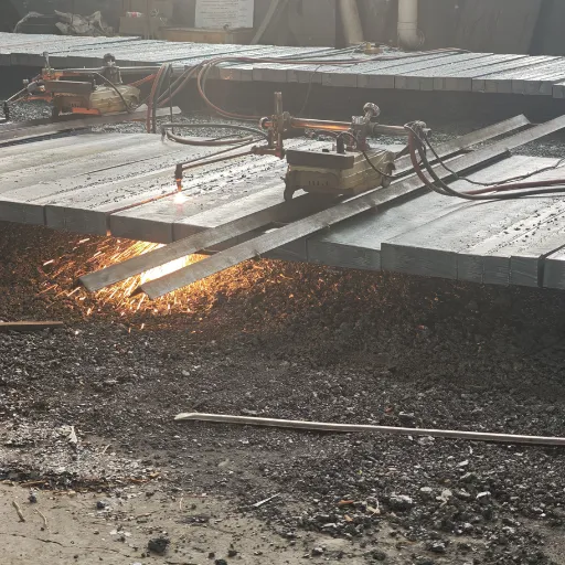
Slitting and Blanking
Large master coils are slit to the correct width, then blanked or stamped into individual laminations. Precision slitting minimizes edge burrs, which can punch through insulation coatings and create interlaminar short circuits. Clean edges also reduce the risk of localized heating and noise in the finished motor.
Stamping and Punching
High-speed progressive dies punch slots, bolt holes, and interlocking features into each lamination. Tool steel selection, punch clearance, and lamination material hardness all affect edge quality. Softer pure iron grades generally allow tighter clearances and longer tool life, while harder high-silicon steels demand more frequent die maintenance.
Annealing and Stress Relief
Stamping introduces mechanical stress that can degrade magnetic properties. A controlled annealing cycle relieves stress, restores grain structure, and reduces hysteresis loss. Some grades require a hydrogen or nitrogen atmosphere to prevent oxidation and maintain surface quality.
Insulation Coatings
Each lamination receives a thin organic or inorganic coating that provides electrical insulation between sheets. Common coatings include C5 organic varnishes and C6 inorganic coatings rated for higher temperatures. Coating thickness is measured in micrometers; too little insulation allows eddy-current bypass, while too much reduces stack factor and effective core area.
Stacking and Bonding
Laminations are stacked using interlocking tabs, welding, riveting, or adhesive bonding. The stacking method affects core stiffness, heat dissipation, and noise. Bonded cores, in which adhesive replaces mechanical fasteners, can reduce interlaminar short circuits and improve efficiency in high-performance motors.
Applications Across Industries
Different industries push motor lamination material in different directions based on their priorities.
Electric Vehicles
EV traction motors demand high power density and efficiency across a wide speed range. Thin-gauge non-oriented electrical steel, often 0.25 mm or thinner, is common in premium EV motors. Some designs also explore amorphous metals or advanced silicon steels to push efficiency toward 97% or higher.
Industrial Motors and Drives
Industrial motors operate continuously in harsh environments, so material selection balances efficiency with durability and cost. Standard NEMA Premium Efficiency motors often use 0.50 mm non-oriented steel, while IE4 and IE5 super-premium designs move to thinner, lower-loss grades.
HVAC and Appliances
Compressors, fans, and pumps run for thousands of hours per year. Even small efficiency gains matter. Manufacturers in this sector often choose mid-grade silicon steel laminations and optimize geometry to hit cost and efficiency targets simultaneously.
Renewable Energy and Power Generation
Wind turbine generators and hydroelectric systems use large laminated cores. These applications may combine non-oriented steel with specialized insulation systems to handle thermal cycling and mechanical stress over decades of service.
Precision Motion and Medical Equipment
High-resolution stepper motors, servo motors, and medical devices frequently use electromagnetic pure iron or nickel-iron alloys. The priority here is stable, repeatable magnetic behavior rather than lowest absolute cost.
Future Trends in Motor Lamination Material
The motor industry is not standing still. Several trends are reshaping how engineers think about motor lamination material.
First, thin-gauge electrical steel is becoming mainstream. As inverter drives and high-speed motors proliferate, 0.20 mm and even 0.15 mm laminations are moving from niche applications into volume production. These thinner materials reduce eddy-current losses but require tighter manufacturing tolerances and stronger insulation.
Second, amorphous and nanocrystalline materials are gaining attention for ultra-high-efficiency motors. These alloys lack the crystalline structure of conventional steel, which gives them extremely low core loss. Challenges include cost, mechanical brittleness, and processing complexity, but the efficiency potential is significant.
Third, sustainability and recycling are influencing material choices. Manufacturers are looking for steels with lower embodied carbon and better end-of-life recyclability. Suppliers who can document environmental credentials may gain preference in procurement decisions.
Finally, digital design tools are accelerating material selection. Finite-element analysis and machine-learning models can predict how a specific motor lamination material will perform in a given design, reducing the need for costly physical prototypes.
Conclusion
Motor lamination material is one of the most important decisions in motor design, yet it often receives less attention than windings, magnets, or controls. The right choice reduces core losses, lowers operating temperature, extends service life, and helps manufacturers meet tightening efficiency regulations. Whether you are designing an EV traction motor, an industrial drive, or a precision servo, understanding electrical steel, silicon steel, and pure iron options gives you a real competitive edge.
Remember these key takeaways:
Core losses depend on both material chemistry and lamination thickness.
Non-oriented electrical steel suits most rotating machines, while grain-oriented steel works only in directional flux paths.
Higher silicon content reduces eddy-current loss but can increase brittleness and tooling wear.
Electromagnetic pure iron such as DT4C delivers exceptional permeability for precision and high-performance applications.
Consistent supply, coating quality, and processing control are just as important as the alloy grade.
If you are sourcing laminations for your next motor project, start by defining your efficiency target, operating frequency, and production volume. Then match those requirements to a material grade that balances performance, manufacturability, and cost. For demanding applications where magnetic precision matters, our electromagnetic pure iron and magnetic materials selection guide can help you find the right fit.
Ready to optimize your motor cores? Request a custom quote for DT4C pure iron laminations →
Recently Posted
-
Magnetic Circuit Analysis: A Practical Engineering Guide
June 26, 2026A 0.5 mm air gap left unaccounted for in a magnetic circuit can increase magnetizing current by 40% and push a prototype relay fro Read More
 -
Solenoid Core Material: How to Choose the Right Pure Iron for Maximum Performance
June 26, 2026A solenoid valve manufacturer in Germany recently replaced their standard steel core pins with electromagnetic pure iron and cut r Read More
 -
Electromagnet Core: A Complete Guide to Materials, Design, and Performance
June 26, 2026When Chen Wei tested his new solenoid valve prototype last March, the numbers made no sense. The coil had 800 turns of 0.4mm coppe Read More
 -
Motor Iron Losses: Causes, Calculations and Reduction Strategies
June 26, 2026Electric motors consume nearly half of the world's electricity, and motor iron losses quietly drain away 15-25% of the energy Read More

Contact Us
Recommended Products
-
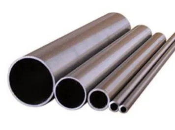
 Seamless Tube With Good Cold Electrical Pure Iron Fittings Hot Workability for Forming Fittings and ConduitsNegotiableMOQ: 1 Ton
 -
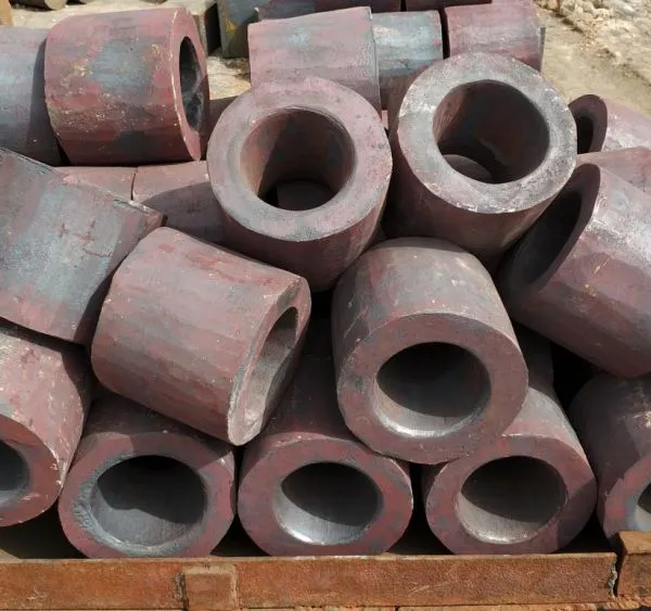
Electromagnetic Pure Iron Forging for Automotive Sensor ManufacturingNegotiableMOQ: 100 Kilograms
-
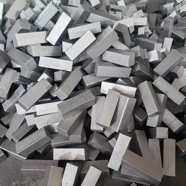
Precision Cut Pure Iron Square Bar High Saturation Induction Raw Material for Generator and RotorNegotiableMOQ: 100 Kilograms
-
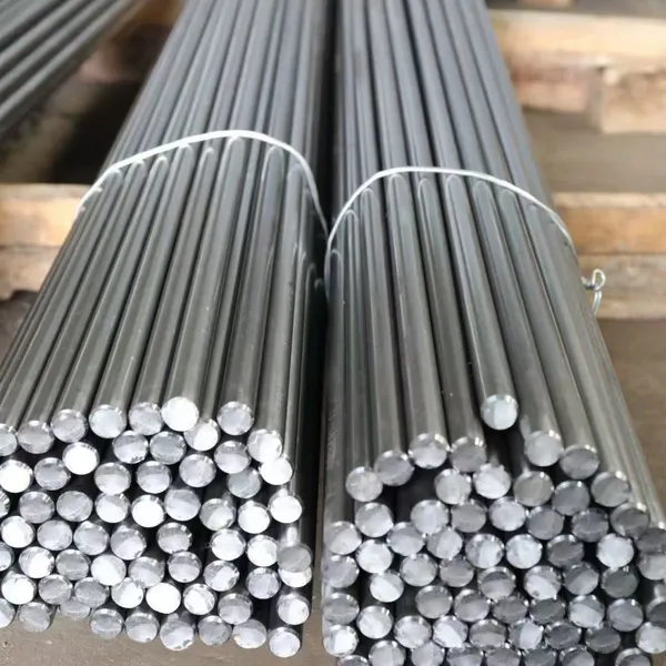
DT4C Super Grade Electromagnetic Pure Iron Bright Bar With Bundle Weight 30-100kg for Easy TransportationNegotiableMOQ: 1 Ton
-
DT4C Electromagnetic Pure Iron Cold-Drawn Wire 0.5mm-6.0mm Diameter for TransformersNegotiableMOQ: 100 Kilograms
-
Industrial Pure Iron Bar for Electromagnetic Relay and Sensor ProductionNegotiableMOQ: 1 Ton
-
Electromagnetic Pure Iron Thin Sheet 0.3mm-0.8mm for Solenoid and Relay ManufacturingNegotiableMOQ: 500 Kilograms
-
Electrical Pure Iron Hot-Rolled Coil for Magnetic Components With Low Iron LossNegotiableMOQ: 1 Ton
-
Low Carbon DT4C Pure Iron Round Bar With 99.8% Fe Content for Electrical ApplicationsNegotiableMOQ: 1 Ton
-
Cold Rolled Pure Iron Slit Coil DT4C Grade Ultra Low Carbon ≤0.004% for Magnetic ComponentsNegotiableMOQ: 1 Ton
-
Low Iron Loss Electromagnetic Pure Iron Hot-Rolled Coil DT4C for Transformer CoresNegotiableMOQ: 1 Ton
-
Soft Magnetic Pure Iron Sheet With Minimum Iron Loss for High-Efficiency MotorsNegotiableMOQ: 1 Ton
-
Electromagnetic Pure Iron Cold Rolled Coil DT4C for High Magnetic Permeability ApplicationsNegotiableMOQ: 1 Ton
-
Industrial Pure Iron Tube Superior Surface Quality Electromagnetic Pure Iron Tube for Welding and Plating ProcessesNegotiableMOQ: 1 Ton
-
DT4 Seamless Pure Iron Tubing for High-Performance Electrical Equipment ApplicationsNegotiableMOQ: 1 Ton
-
DT4C Iron Wire Rod for Precision Magnetic Shielding ApplicationsNegotiableMOQ: 100 Kilograms
-
Industrial Pure Iron Fittings DT4 Pure Iron Seamless Tube With Low Hysteresis Loss for Electromagnetic SystemsNegotiableMOQ: 1 Ton
-
DT4C Cold Rolled Coil Slitting for Electrical Enclosure ManufacturingNegotiableMOQ: 1 Ton
-
Anti Rust Coated Pure Iron Square Bar Low Carbon Raw Material for Welding and Forging Magnetic PartsNegotiableMOQ: 100 Kilograms
-
DT4 Pure Iron Cold-Drawn Wire 0.5mm-6.0mm Diameter for Precision EngineeringNegotiableMOQ: 500 Kilograms