
 Business License

Motor Iron Losses: Causes, Calculations and Reduction Strategies
Electric motors consume nearly half of the world's electricity, and motor iron losses quietly drain away 15-25% of the energy that should reach the output shaft. For manufacturers running thousands of motors across production lines, that invisible waste adds up to thousands of dollars in unnecessary electricity costs every year.
If you design, source, or maintain electric motors, you already know that efficiency ratings matter. But the real question is whether you are selecting the right core materials and construction methods to keep iron losses as low as possible. In this guide, you will learn exactly what motor iron losses are, how they split into hysteresis loss and eddy current loss, how to estimate them, and which soft magnetic materials can help you build more efficient motors.
We will start with the physics behind motor iron losses, move through practical calculation methods, and finish with material selection strategies you can apply immediately.
What Are Motor Iron Losses?
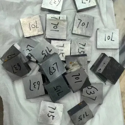
Motor iron losses, also called core losses or no-load losses, are the energy dissipated as heat inside the magnetic core of an electric motor. These losses occur whenever the stator or rotor core is subjected to a changing magnetic field during normal operation.
Unlike copper losses, which depend on the current flowing through windings, motor iron losses exist even when a motor runs without mechanical load. They represent energy that never makes it to the rotor. Because motors operate for thousands of hours per year, even small reductions in motor iron losses translate into measurable cost savings and cooler running equipment.
Why Motor Iron Losses Matter for Manufacturers
High motor iron losses create three practical problems on the factory floor:
Higher electricity bills: Every watt lost as heat is a watt that did not perform useful work.
Reduced motor life: Excess heat accelerates insulation aging and bearing lubricant breakdown.
Lower power density: Motors with high core losses must be oversized to deliver the same output.
For original equipment manufacturers (OEMs) and motor rewind shops, specifying low-loss core materials is one of the most effective ways to improve product competitiveness without redesigning the entire machine.
The Two Main Types of Motor Iron Losses
Motor iron losses split into two distinct physical mechanisms:
Hysteresis loss: Energy consumed to reorient magnetic domains each time the magnetic field reverses direction.
Eddy current loss: Energy dissipated by circulating electrical currents induced inside the core material itself.
Understanding both mechanisms is essential because they respond differently to frequency, flux density, and material grade. A design change that reduces one type of loss might have little effect on the other.
Hysteresis Loss: The Magnetic Memory Problem
Hysteresis loss comes from the fact that magnetic domains inside iron do not flip instantly. Each time the alternating current reverses, the domains must physically rotate against internal friction. That friction converts magnetic energy into heat.
The area inside the B-H curve of a material represents the energy lost per cycle. Materials with a narrow hysteresis loop, such as high-purity electromagnetic iron, lose less energy during each reversal than standard structural steels with wider loops.
Chen Wei, a motor design engineer at a pump OEM in Jiangsu, noticed that a new stator material specification was supposed to reduce core losses by 8%. When the first production batch arrived, the motors ran 5°C hotter than expected. Testing showed the supplier had substituted a lower-grade lamination steel with higher hysteresis loss. Switching back to the specified ultra-low carbon pure iron brought temperatures down and restored the efficiency target.
How Frequency Affects Hysteresis Loss
Hysteresis loss increases directly with frequency. If you double the operating frequency while holding flux density constant, the hysteresis component of motor iron losses also doubles. This is why high-speed motors and variable-frequency drive (VFD) applications place extra emphasis on low-hysteresis materials.
Flux Density and Hysteresis Loss
Hysteresis loss scales roughly with flux density raised to a power between 1.6 and 2.5, depending on the material. Operating a motor closer to magnetic saturation might save copper by allowing fewer turns, but it sharply increases hysteresis loss. The best designs balance copper and iron losses for the target duty cycle.
Eddy Current Loss: How Frequency and Thickness Drive Waste
Eddy current loss arises because a changing magnetic field induces voltage inside the conductive core material. That voltage drives small circulating currents, which resist the magnetic change and produce heat. The faster the field changes, the stronger the eddy currents become.
Motor cores are built from thin, insulated laminations rather than solid blocks of iron precisely because laminations interrupt eddy current paths. The thinner the lamination, the smaller the loops currents can form, and the lower the eddy current loss becomes.
The Role of Lamination Thickness
Eddy current loss is proportional to the square of lamination thickness. Reducing lamination thickness from 0.50 mm to 0.35 mm can cut the eddy current component by roughly half, assuming the same material and insulation quality. Premium high-efficiency motors often use 0.20-0.35 mm laminations to keep motor iron losses low at higher frequencies.
However, thinner laminations increase material cost and can reduce stacking factor if insulation layers become too thick. The optimal thickness depends on motor speed, power rating, and target efficiency class.
Silicon Steel vs. Pure Iron Considerations
Most mass-market motors use silicon steel laminations because silicon increases electrical resistivity, which reduces eddy currents. But adding silicon also reduces magnetic permeability at high flux densities.
For applications requiring maximum magnetic permeability and minimal hysteresis loss, soft magnetic pure iron and ultra-low carbon grades like DT4C pure iron can outperform standard silicon steel. These materials are especially valuable in precision motors, high-performance servo motors, and specialized electromagnetic components where low motor iron losses matter more than raw material cost.
How Material Grade Affects Motor Iron Losses
The chemical composition and processing history of the core material set the practical lower limit for motor iron losses. Even with perfect lamination design, a poor core material will always waste more energy than an optimized grade.
Carbon Content and Magnetic Properties
Carbon is one of the most damaging impurities in soft magnetic materials. Carbon atoms pin magnetic domain walls, which increases coercivity and widens the hysteresis loop. Ultra-low carbon grades with carbon content at or below 0.004%, such as DT4C pure iron, offer significantly lower hysteresis loss than higher-carbon alternatives.
DT4C electromagnetic pure iron also provides high magnetic permeability and low coercive force, making it ideal for applications where rapid magnetic switching and low motor iron losses are both required.
Grain Orientation and Texture
Cold-rolled grain-oriented (CRGO) electrical steel reduces losses by aligning crystal grains so that the easy magnetization direction lies along the rolling direction. Non-oriented grades are used where flux travels in multiple directions, such as in rotating machine stators.
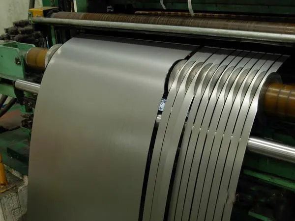
For manufacturers seeking low-loss performance without the directional constraints of CRGO, cold-rolled pure iron sheets and slit coils provide an attractive middle ground. They combine good multi-directional magnetic properties with the ultra-low hysteresis loss of high-purity iron.
Want to compare core materials for your next motor project? Explore our guide to magnetic materials selection for a detailed breakdown of grades and applications.
Calculating Motor Iron Losses in Practice
Engineers usually estimate motor iron losses using empirical models and then validate those estimates with laboratory testing. The most common approach combines the Steinmetz equation with loss separation techniques.
The Steinmetz Equation
The classical Steinmetz equation expresses core loss per unit mass as:
Pcore=kh⋅f⋅Bn+ke⋅(f⋅B)2Pcore=kh⋅f⋅Bn+ke⋅(f⋅B)2
Where:
PcorePcore is the core loss per unit mass
ff is the electrical frequency
BB is the peak flux density
khkh and keke are material-specific hysteresis and eddy current coefficients
nn is the Steinmetz exponent, typically 1.6 to 2.5
The first term represents hysteresis loss, and the second term represents eddy current loss. Modern design software includes material loss curves that are more accurate than the simple Steinmetz form, especially at the non-sinusoidal flux waveforms created by VFDs.
Separating Loss Components
Motor testing standards often separate no-load losses into three buckets:
Core losses: Hysteresis and eddy current losses in the magnetic circuit.
Friction and windage losses: Mechanical losses from bearings and rotor fan action.
Stray load losses: Additional losses that appear under load from flux leakage and harmonic currents.
By running a motor at no load and varying the voltage, engineers can plot the core loss curve and extrapolate the constant mechanical losses. This separation helps identify whether motor iron losses are the dominant source of inefficiency.
Testing and Measurement Methods
Common test methods for quantifying motor iron losses include:
Epstein frame test: Measures core loss of flat lamination samples under controlled sinusoidal flux.
Single sheet tester: Tests larger samples than the Epstein frame and better represents real processing conditions.
Calorimetric method: Measures heat output directly, which is useful for complete motors under load.
Input-output method: Compares electrical input power to mechanical output power and accounts for all losses together.
For manufacturers sourcing laminations, requesting certified Epstein frame data from the material supplier ensures that quoted loss values are comparable between batches.
Strategies to Reduce Motor Iron Losses
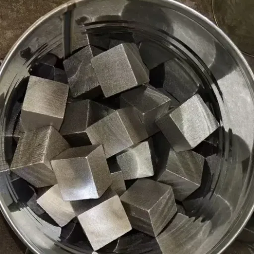
Reducing motor iron losses requires a systems approach. No single change delivers dramatic results, but combining several improvements produces meaningful efficiency gains.
1. Select Low-Loss Core Materials
Start with a core material matched to the application. For premium efficiency motors, consider:
Ultra-low carbon pure iron such as DT4C for high-permeability, low-hysteresis designs.
Thin-gauge silicon steel for high-frequency or high-speed motors.
Cold-rolled non-oriented electrical steel for general-purpose rotating machines.
2. Optimize Lamination Thickness and Insulation
Use the thinnest practical lamination for the operating frequency. Verify that the interlaminar insulation remains intact after punching and annealing. Damaged insulation creates interlaminar shorts, which dramatically increase eddy current loss.
3. Control Flux Density
Avoid operating the core too close to saturation. Redesigning the magnetic circuit to use slightly more material can lower flux density enough to reduce hysteresis loss faster than the extra material adds cost.
4. Minimize Harmonic Content
VFDs and inverter-fed motors often experience harmonic flux components that increase motor iron losses beyond sinusoidal estimates. Selecting drives with appropriate carrier frequencies and using motors designed for inverter duty can limit these additional losses.
5. Improve Stacking and Assembly Processes
Burr formation during lamination punching, excessive clamping pressure, and misaligned stacks all increase localized core losses. Clean punching tools, proper annealing, and controlled stacking pressure help preserve the material's designed magnetic performance.
When Liu Mei took over sourcing for a small motor factory in Zhejiang, her biggest win came from switching from a generic low-carbon steel to a specified DT4C electromagnetic pure iron for a specialty servo motor line. The change reduced no-load core losses by 12% and allowed the engineering team to reduce lamination thickness without exceeding temperature rise limits. The material cost was higher per kilogram, but the overall motor ran cooler and qualified for a higher efficiency band.
Selecting the Right Soft Magnetic Material for Your Motor
Choosing between silicon steel, pure iron, and specialty alloys depends on the motor's operating conditions, cost targets, and performance requirements. The table below summarizes the trade-offs.
| Material | Best For | Hysteresis Loss | Eddy Current Loss | Relative Cost |
|---|---|---|---|---|
| Standard silicon steel | General-purpose induction motors | Low | Moderate | Low |
| Thin-gauge silicon steel | High-frequency motors, VFD applications | Low | Low | Medium |
| CRGO electrical steel | Transformers, flux paths | Very low | Very low | High |
| DT4C pure iron | Servo motors, relays, high-permeability parts | Very low | Low | Medium-high |
| Nickel-iron alloys | Precision instruments | Very low | Low | Very high |
For manufacturers focused on reducing motor iron losses in precision motors, electromagnetic relays, or solenoid assemblies, DT4C pure iron offers a strong balance of low hysteresis loss, high permeability, and processability.
Need DT4C pure iron cut to your exact motor specifications? Contact our engineering team for a custom quote on precision-slit coils, cold-rolled sheets, and custom-cut bars.
The Bottom Line on Motor Iron Losses
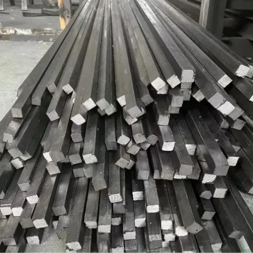
Motor iron losses are an unavoidable part of electromagnetic energy conversion, but they are not a fixed cost. By understanding the split between hysteresis loss and eddy current loss, selecting the right lamination thickness, and choosing core materials suited to the application, manufacturers can build motors that run cooler, consume less electricity, and last longer.
Key takeaways from this guide:
Motor iron losses occur as hysteresis loss and eddy current loss inside the magnetic core.
Hysteresis loss depends on material purity, grain structure, and flux density.
Eddy current loss depends on lamination thickness, frequency, and material resistivity.
Ultra-low carbon grades such as DT4C pure iron reduce hysteresis loss and improve magnetic permeability.
Combining material selection with proper stacking and assembly practices delivers the best efficiency gains.
Certified testing methods such as Epstein frame tests help verify material performance before production.
The motors you specify today will determine your energy costs for years to come. Small improvements in core material selection can compound into significant savings across an entire installed base.
Ready to reduce motor iron losses in your next design? Reach out to Shanxi Jurun Technology to discuss your material requirements. We supply DT4C and other electromagnetic pure iron grades in coils, sheets, bars, and custom-cut forms to support efficient motor manufacturing worldwide.
Recently Posted
-
Shanxi Jurun Technology: Your Electromagnetic Pure Iron Partner from Taiyuan, China's Pure Iron Prod
August 14, 2026When an international buyer searches for electromagnetic pure iron, they are not just looking for a material. They are looking for Read More
 -
Cold Drawing Process for Electromagnetic Pure Iron Wire: How Wire Rod Becomes Precision Cold-Drawn W
August 13, 2026Not long ago, a solenoid valve manufacturer in Italy received a shipment of 5.5 mm electromagnetic pure iron cold-drawn wire inten Read More
 -
How to Choose a Food Vacuum Sealer Supplier in China: 8 Evaluation Criteria
August 13, 2026An e-commerce brand owner in the UK contacted us some time ago after a supplier relationship fell apart. They had sourced roughly Read More
 -
Electromagnetic Pure Iron for Relay Manufacturing: Material Requirements, Grade Selection, and Case
August 13, 2026Some time ago, a relay production line in Zhejiang province began experiencing a puzzling failure pattern. Roughly 3 out of every
Read More

Contact Us
Recommended Products
-
 Seamless Tube With Good Cold Electrical Pure Iron Fittings Hot Workability for Forming Fittings and ConduitsNegotiableMOQ: 1 Ton
 -
Electromagnetic Pure Iron Forging for Automotive Sensor ManufacturingNegotiableMOQ: 100 Kilograms
-
Precision Cut Pure Iron Square Bar High Saturation Induction Raw Material for Generator and RotorNegotiableMOQ: 100 Kilograms
-
DT4C Super Grade Electromagnetic Pure Iron Bright Bar With Bundle Weight 30-100kg for Easy TransportationNegotiableMOQ: 1 Ton
-
DT4C Electromagnetic Pure Iron Cold-Drawn Wire 0.5mm-6.0mm Diameter for TransformersNegotiableMOQ: 100 Kilograms
-
Industrial Pure Iron Bar for Electromagnetic Relay and Sensor ProductionNegotiableMOQ: 1 Ton
-
Electromagnetic Pure Iron Thin Sheet 0.3mm-0.8mm for Solenoid and Relay ManufacturingNegotiableMOQ: 500 Kilograms
-
Electrical Pure Iron Hot-Rolled Coil for Magnetic Components With Low Iron LossNegotiableMOQ: 1 Ton
-
Low Carbon DT4C Pure Iron Round Bar With 99.8% Fe Content for Electrical ApplicationsNegotiableMOQ: 1 Ton
-
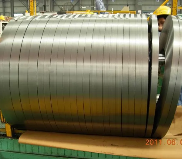
Cold Rolled Pure Iron Slit Coil DT4C Grade Ultra Low Carbon ≤0.004% for Magnetic ComponentsNegotiableMOQ: 1 Ton
-
Low Iron Loss Electromagnetic Pure Iron Hot-Rolled Coil DT4C for Transformer CoresNegotiableMOQ: 1 Ton
-
Soft Magnetic Pure Iron Sheet With Minimum Iron Loss for High-Efficiency MotorsNegotiableMOQ: 1 Ton
-
Electromagnetic Pure Iron Cold Rolled Coil DT4C for High Magnetic Permeability ApplicationsNegotiableMOQ: 1 Ton
-
Industrial Pure Iron Tube Superior Surface Quality Electromagnetic Pure Iron Tube for Welding and Plating ProcessesNegotiableMOQ: 1 Ton
-
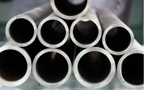
DT4 Seamless Pure Iron Tubing for High-Performance Electrical Equipment ApplicationsNegotiableMOQ: 1 Ton
-
DT4C Iron Wire Rod for Precision Magnetic Shielding ApplicationsNegotiableMOQ: 100 Kilograms
-
Industrial Pure Iron Fittings DT4 Pure Iron Seamless Tube With Low Hysteresis Loss for Electromagnetic SystemsNegotiableMOQ: 1 Ton
-
DT4C Cold Rolled Coil Slitting for Electrical Enclosure ManufacturingNegotiableMOQ: 1 Ton
-
Anti Rust Coated Pure Iron Square Bar Low Carbon Raw Material for Welding and Forging Magnetic PartsNegotiableMOQ: 100 Kilograms
-
DT4 Pure Iron Cold-Drawn Wire 0.5mm-6.0mm Diameter for Precision EngineeringNegotiableMOQ: 500 Kilograms