Rotor Core Material: A Complete Guide for High-Performance Motors
What if your motor is losing torque before it ever reaches the load?
Every motor designer has faced the puzzle: windings are optimized, the drive is tuned, and the magnets are top grade, yet the machine runs hotter and noisier than expected. The hidden culprit is often the rotor core material. While the stator gets most of the attention in motor design reviews, the rotor must spin, carry magnetic flux, and survive mechanical stress, all at the same time. The metal inside that rotating stack directly affects efficiency, temperature rise, acoustic noise, and reliability.
In this guide, you will learn how rotor core material influences motor performance, when standard electrical steel is the right choice, and when electromagnetic pure iron delivers an advantage. We will walk through material properties, lamination design, high-speed considerations, and validation testing so you can specify the best motor core material for your next design.
What a Rotor Core Actually Does
A rotor core is the rotating magnetic heart of an electric motor or generator. It carries the magnetic flux generated by the stator windings and converts electromagnetic energy into mechanical torque. In an induction motor, the rotor core supports either a squirrel-cage winding or a wound winding. In permanent-magnet motors, it holds the magnets and channels flux across the air gap.
Because the rotor spins, its core faces demands that the stator does not. Centrifugal force tries to pull laminations apart. Vibration and torque pulsations create fatigue loads. Eddy currents generated by time-varying magnetic fields produce heat that must be removed while the rotor is moving. These factors make rotor core material selection a balance between magnetic performance and mechanical integrity.
The core is almost always built from thin laminations rather than a solid piece. Each lamination is electrically insulated from the next to break up eddy current paths. Thinner laminations reduce these circulating currents, but they also increase part count, stacking time, and cost. The right lamination thickness depends on operating frequency, pole count, and thermal budget.
When Tom, a senior engineer at a Michigan-based compressor manufacturer, redesigned a 7.5 kW induction motor for variable-speed operation, he kept the original 0.50 mm silicon steel stator but overlooked the rotor. At low speeds the motor ran fine, but above 90 Hz the rotor temperature climbed 22°C above the stator. The rotor laminations were simply too thick for the harmonics introduced by the inverter. After switching to thinner rotor lamination steel and adding a better inter-laminar insulation, the temperature rise dropped within limits and efficiency improved by 1.1 percentage points. The lesson was clear: the rotor deserves the same material scrutiny as the stator.
Magnetic Properties That Matter in a Rotor Core
Four magnetic properties dominate rotor core material selection:
Magnetic permeability: A high-permeability material channels more flux with less magnetizing current, improving torque per ampere.
Saturation induction: The maximum flux density the material can support before saturating. Higher saturation allows smaller rotor diameters for the same torque.
Core loss (iron loss): Energy lost as heat through hysteresis and eddy currents. Lower core loss means cooler operation and higher efficiency.
Coercivity: The field required to reverse magnetization. Low coercivity reduces hysteresis loss, which is especially valuable in motors that cycle through magnetic states rapidly.
Mechanical properties also matter. Yield strength, fatigue resistance, and thermal expansion influence whether the rotor can survive high-speed operation and repeated thermal cycling. A material with outstanding magnetic properties but poor mechanical strength may require heavier retaining sleeves or larger shafts, offsetting the magnetic benefit.
Electrical Steel: The Industry Standard
Electrical steel, also called silicon steel or lamination steel, is the most common rotor core material in mass-produced motors. It is a low-carbon steel alloyed with silicon, typically between 0.5% and 6.5%, to increase electrical resistivity and suppress eddy current losses.
For rotating machines, non-oriented electrical steel is the standard choice. Its magnetic properties are similar in every direction, which is important because flux direction changes constantly as the rotor turns. Oriented electrical steel, optimized for one rolling direction, is reserved for transformers where flux follows a predictable path.
Grades and Thickness
Electrical steel grades are identified by core loss at a specific flux density and frequency. A designation such as 35A230 or M19 tells an engineer the expected loss level and lamination thickness. In general, thinner grades offer lower losses but cost more and may be harder to handle during high-speed stamping.
Common rotor lamination thicknesses include:
0.50 mm: Widely used in industrial motors and pumps where cost matters and frequencies are moderate.
0.35 mm: Common in premium-efficiency motors and servo drives where lower loss justifies the price.
0.20 mm or thinner: Used in high-speed motors, aerospace actuators, and traction drives where eddy current losses dominate.
Coatings and Insulation
Each lamination receives an insulating coating to prevent electrical contact between layers. The coating must survive punching, annealing, stacking, and long exposure to motor varnish and elevated temperatures. If the insulation degrades, laminations short together locally, creating hot spots and increasing core loss.
For rotor applications, coating durability is especially important because centrifugal force and thermal expansion put mechanical stress on the lamination edges. A coating that flakes during punching or handling can create bare spots that defeat the purpose of lamination.
When Electrical Steel Reaches Its Limit
Standard electrical steel is the right choice for many motors, but it is not always the best rotor core material when performance requirements push higher. In high-speed motors, precision servos, and specialty magnetic assemblies, the limitations of silicon steel become visible.
The first limitation is mechanical. Silicon makes steel harder and more brittle. At very high rotational speeds, silicon steel laminations may not have enough strength to withstand centrifugal stress without heavy retaining structures. The second limitation is magnetic. Silicon additions reduce saturation induction slightly compared to pure iron. In compact, high-torque designs, that small reduction can force a larger rotor diameter.
The third limitation is impurity content. Residual carbon, nitrogen, and sulfur increase hysteresis loss and reduce permeability. Even levels measured in hundredths of a percent matter when efficiency targets are tight. Applications such as aerospace, medical equipment, and precision robotics often demand cleaner materials.
A design team at a Dutch drone motor manufacturer ran into this problem while developing a 30,000 rpm brushless motor. Their first prototype used a standard non-oriented silicon steel rotor. Bench tests showed excessive heat and rapid demagnetization of the surface-mounted magnets. After switching to a high-purity electromagnetic pure iron rotor core, core loss dropped by approximately one third and magnet temperatures fell enough to allow a smaller magnet volume. The switch paid for itself in reduced magnet and cooling hardware costs.
Electromagnetic Pure Iron as a Rotor Core Material
Electromagnetic pure iron is a soft magnetic material produced with extremely low carbon and impurity levels. Grades such as DT4C pure iron are manufactured with carbon content at or below 0.004%. Instead of relying on silicon to control losses, pure iron achieves performance through metallurgical cleanliness.
For rotor cores, electromagnetic pure iron offers several practical advantages:
High permeability at low and moderate fields: It magnetizes easily, which improves torque production in small motors and sensors.
Low coercivity: The narrow hysteresis loop means less energy is wasted each time the magnetic field reverses.
High saturation induction: Pure iron can carry more flux than many silicon steels before saturating, supporting compact rotor designs.
Excellent ductility and machinability: Without silicon-induced brittleness, pure iron can be machined, forged, or stamped into complex rotor shapes.
Good weldability and plating response: Rotor components often require welding, brazing, or coatings for corrosion protection and balance.
Common Forms for Rotor Manufacturing
Electromagnetic pure iron is supplied in forms that match different rotor production routes:
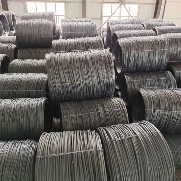
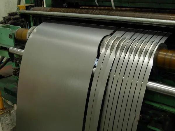
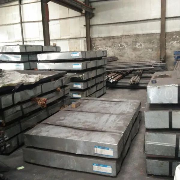
Cold-rolled sheets and thin strips for stamped laminations
Hot-rolled coils for larger rotor cores and magnetic poles
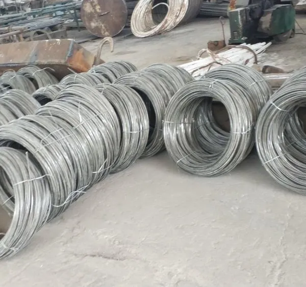
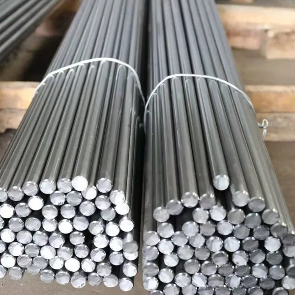
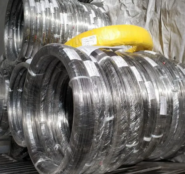
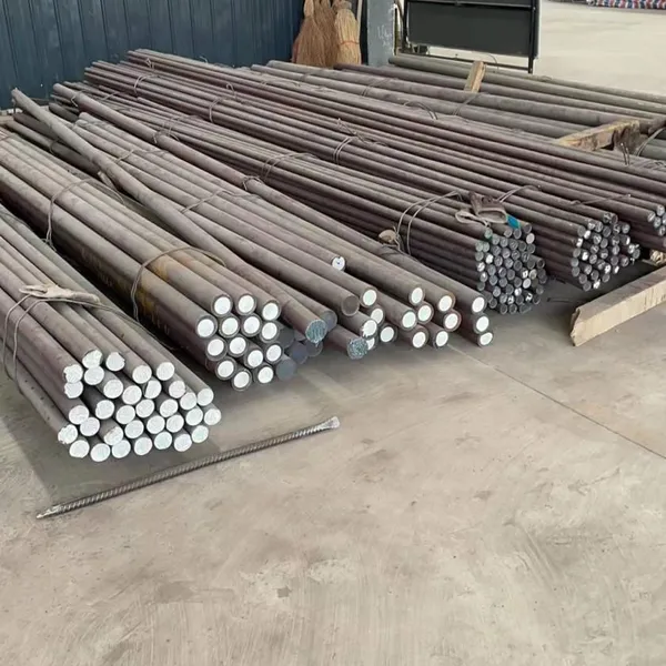
Cold-drawn bars and wire for machined rotor components, shafts, and pole pieces
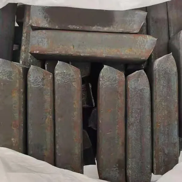
Forged rounds for high-stress rotor segments and specialty hub assemblies
If your design combines high magnetic performance with mechanical forming operations, pure iron often provides a cleaner path than conventional silicon steel laminations.
Rotor Design Factors That Affect Material Choice
Selecting a rotor core material is only part of the equation. The lamination geometry, stacking method, and cooling strategy also determine final performance.
Lamination Thickness
Thinner laminations reduce eddy current losses because each layer experiences a smaller change in flux and because the insulation between layers interrupts current paths. However, thinner material is more expensive, harder to punch cleanly, and produces stacks with more interfaces. For rotor cores, the practical minimum thickness is often set by mechanical strength rather than loss targets alone.
Skewing and Slot Design
Rotor laminations are sometimes skewed relative to the shaft axis to reduce cogging torque and acoustic noise. Skewing changes the effective magnetic path length and can influence material selection. Materials with higher permeability tolerate the longer flux path with less magnetizing current.
Slot shape and fill factor affect flux distribution. In squirrel-cage rotors, the bars and end rings must be matched to the lamination steel to avoid localized saturation. A mismatch can create harmonic losses that no material can fix.
Stacking and Retention
Rotor laminations must be held together while spinning at high speed. Common methods include:
Welding: Fast and strong, though heat can damage local insulation.
Interlocking tabs: No extra fasteners, but stress concentrations can weaken the stack.
Bonding: Provides excellent electrical isolation and damping, though process control is critical.
Keyed shafts and end plates: Common in large motors and generators where mechanical reliability comes first.
The stacking method affects both magnetic and mechanical performance. A bonded pure iron stack, for example, may offer lower eddy current loss than a welded silicon steel stack even if the base materials have similar nominal properties.
Cooling and Thermal Management
Rotors are harder to cool than stators because they rotate and are often enclosed. The rotor core material must tolerate the resulting temperatures without excessive loss growth. Some materials exhibit much higher core loss at elevated temperatures, so supplier data should be checked at the actual operating temperature, not just room temperature.
High-Speed and Specialty Rotor Considerations
High-speed motors for turbochargers, flywheels, compressors, and spindles place extraordinary demands on rotor core material. At rotational speeds above 10,000 rpm, centrifugal stress can exceed the yield strength of conventional lamination steels. Designers may need to use high-strength magnetic alloys, composite retaining sleeves, or solid rotor constructions.
In some high-speed designs, engineers move away from laminated rotors entirely and use solid soft magnetic materials. Solid rotors eliminate inter-laminar insulation but require materials with low eddy current loss and enough mechanical strength to spin. Electromagnetic pure iron and certain cobalt-iron alloys are candidates here, though each has cost and manufacturability trade-offs.
Permanent-magnet rotors introduce another consideration. The magnets are often brittle and must be retained against centrifugal force. The rotor core material must provide a stable magnetic path without adding unnecessary mass. High saturation induction helps here because it allows a smaller core cross-section, reducing inertia and centrifugal load.
Testing and Validating Rotor Core Performance
Supplier data sheets are a starting point, but real rotor performance depends on lamination design, stacking quality, operating temperature, and drive waveform. Validation should include both material-level and assembly-level tests.
Material-Level Tests
Epstein frame or single-sheet tester: Measures core loss and permeability under controlled sinusoidal excitation.
Ring sample testing: Evaluates toroidal samples after annealing to assess intrinsic magnetic properties.
Mechanical testing: Tensile, fatigue, and hardness data for high-speed or high-stress designs.
Assembly-Level Tests
Core loss on stacked samples: Captures the effect of punching burrs, coating damage, and stacking pressure.
Temperature rise testing: Reveals hotspot formation under actual operating conditions.
Efficiency mapping: Shows how losses vary with speed and load across the operating envelope.
Spin testing: For high-speed rotors, confirms mechanical integrity at overspeed conditions.
A team at a Korean machine-tool builder tested three candidate rotor core material options for a new 24,000 rpm spindle motor. The lowest-loss silicon steel looked best in the Epstein frame, but after punching and stacking, its advantage disappeared due to coating damage. A high-purity pure iron sample, annealed after stamping and bonded into a stack, delivered the lowest total loss in the assembled rotor and passed spin testing without a retaining sleeve upgrade. The paper data had not predicted the winner.
Choosing the Right Rotor Core Material
Use the following framework to narrow your selection.
Operating Frequency and Speed
At line frequency and moderate speed, standard non-oriented electrical steel is cost-effective. As frequency or rotational speed rises, thinner laminations and lower-loss grades become necessary. For very high-speed rotors, evaluate high-purity iron, cobalt-iron alloys, or solid rotor materials.
Torque Density and Saturation
Motors that must deliver high torque in a small package need materials with high saturation induction. Electromagnetic pure iron and cobalt-iron alloys offer higher saturation than most silicon steels, enabling smaller rotor diameters.
Loss Budget
If efficiency certification, battery range, or thermal constraints are tight, prioritize low core loss. Compare materials at the actual frequency, flux density, and temperature of your application. Small differences in loss compound over the motor lifetime.
Manufacturing Route
Stamped laminations favor materials with good punchability. If the rotor requires machining, welding, forging, or custom shaping, pure iron's ductility and weldability become significant advantages.
Cost and Supply Reliability
Premium grades cost more than commodity steel, but they can reduce overall system cost by allowing smaller magnets, less cooling hardware, or higher power density. Sourcing directly from a producer with in-house slitting, cutting, and processing capabilities can reduce lead-time risk and improve dimensional control.
Need help matching a rotor core material to your motor design? Contact our engineering team to discuss DT4C pure iron, custom slit coils, and cut-to-length bars tailored to your lamination and machining needs.
Emerging Trends in Rotor Core Materials
The global push toward electrification is reshaping motor design and rotor core material selection. Three trends stand out.
Higher Efficiency and Power Density
Regulations such as IE4, IE5, and regional EV efficiency standards are pushing manufacturers toward lower-loss materials. In many cases, the only way to meet these standards is to improve core material performance while also optimizing lamination design.
High-Speed Electrification
Electric vehicles, aircraft actuators, and industrial spindles demand motors that spin faster and pack more torque into less space. These requirements challenge conventional silicon steel and create opportunities for advanced soft magnetic materials such as pure iron and cobalt-iron alloys.
Sustainable Manufacturing
Material yield, scrap reduction, and recycling are becoming selection criteria. Sourcing pure iron raw material with reliable quality and custom dimensions helps reduce stamping scrap and machining waste. Lower scrap rates also mean lower embodied energy per finished motor.
Conclusion: Match the Rotor Core Material to the Mission
The rotor core material you choose is one of the most consequential decisions in motor design. It governs not only magnetic performance but also thermal behavior, mechanical reliability, and acoustic signature. Standard electrical steel remains the right choice for many applications, but it is not the only option.
When your design demands high permeability, low coercivity, high saturation, or superior machinability, electromagnetic pure iron deserves serious consideration. Grades such as DT4C pure iron offer a combination of magnetic cleanliness and manufacturing flexibility that conventional silicon steel cannot always match.
Here are the key takeaways:
The rotor core must handle magnetic flux, mechanical stress, and thermal loads simultaneously.
Electrical steel is the mainstream motor core material, selected by grade and lamination thickness.
Electromagnetic pure iron excels where permeability, low coercivity, and machinability are critical.
Lamination thickness, stacking method, skew, and cooling all influence real-world rotor performance.
Always validate materials on assembled rotors under actual operating conditions, not just on data sheets.
Ready to optimize your next rotor design? Explore our guide to electrical pure iron applications and learn how to select the right magnetic materials for your motor. For custom-cut pure iron laminations, coils, and forged rounds delivered from Taiyuan's production hub, request a quote today.
Recently Posted
-
Transformer Calculation: A Practical Guide for Core Design and Material Selection
June 30, 2026A 2-millimeter error in core cross-section can quietly drain thousands of dollars from a transformer production run. That is exact Read More
 -
Magnetic Flux: A Complete Guide for Electrical Engineering Applications
June 30, 2026In late 2024, a power equipment manufacturer in Poland received a shipment of transformer cores that looked perfect on paper. The Read More
 -
Magnetic Field Strength: A Practical Guide for Electromagnetic Design
June 30, 2026When Wang Chen's solenoid valve line began missing stroke targets in March 2026, his team suspected the usual suspects: worn s Read More
 -
AC Electromagnet: Design, Applications, and Material Selection Guide
June 30, 2026Last quarter, a relay manufacturer in Dongguan shipped 5,000 solenoid valves to a European automotive client. Two weeks after inst Read More

Contact Us
Recommended Products
-
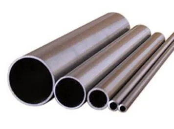
 Seamless Tube With Good Cold Electrical Pure Iron Fittings Hot Workability for Forming Fittings and ConduitsNegotiableMOQ: 1 Ton
 -
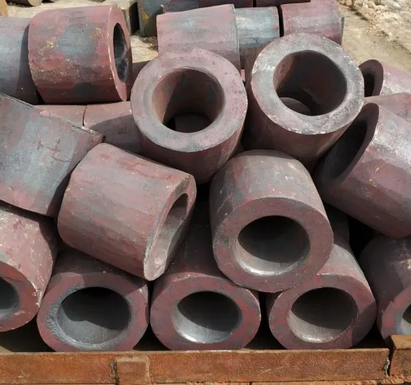
Electromagnetic Pure Iron Forging for Automotive Sensor ManufacturingNegotiableMOQ: 100 Kilograms
-
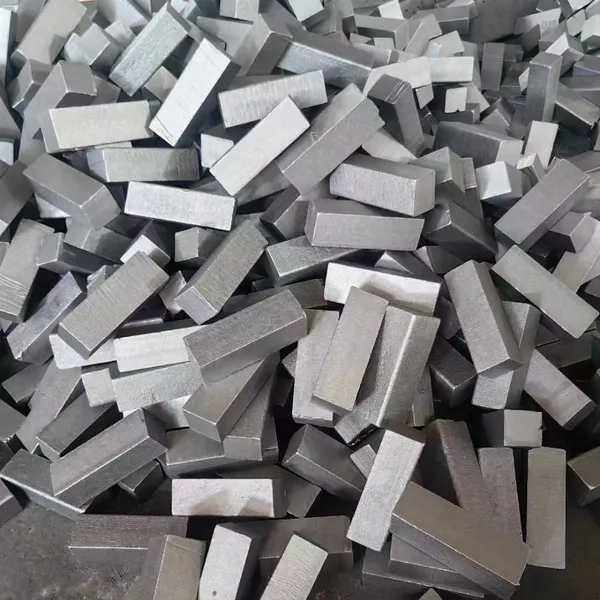
Precision Cut Pure Iron Square Bar High Saturation Induction Raw Material for Generator and RotorNegotiableMOQ: 100 Kilograms
-
DT4C Super Grade Electromagnetic Pure Iron Bright Bar With Bundle Weight 30-100kg for Easy TransportationNegotiableMOQ: 1 Ton
-
DT4C Electromagnetic Pure Iron Cold-Drawn Wire 0.5mm-6.0mm Diameter for TransformersNegotiableMOQ: 100 Kilograms
-
Industrial Pure Iron Bar for Electromagnetic Relay and Sensor ProductionNegotiableMOQ: 1 Ton
-
Electromagnetic Pure Iron Thin Sheet 0.3mm-0.8mm for Solenoid and Relay ManufacturingNegotiableMOQ: 500 Kilograms
-
Electrical Pure Iron Hot-Rolled Coil for Magnetic Components With Low Iron LossNegotiableMOQ: 1 Ton
-
Low Carbon DT4C Pure Iron Round Bar With 99.8% Fe Content for Electrical ApplicationsNegotiableMOQ: 1 Ton
-
Cold Rolled Pure Iron Slit Coil DT4C Grade Ultra Low Carbon ≤0.004% for Magnetic ComponentsNegotiableMOQ: 1 Ton
-
Low Iron Loss Electromagnetic Pure Iron Hot-Rolled Coil DT4C for Transformer CoresNegotiableMOQ: 1 Ton
-
Soft Magnetic Pure Iron Sheet With Minimum Iron Loss for High-Efficiency MotorsNegotiableMOQ: 1 Ton
-
Electromagnetic Pure Iron Cold Rolled Coil DT4C for High Magnetic Permeability ApplicationsNegotiableMOQ: 1 Ton
-
Industrial Pure Iron Tube Superior Surface Quality Electromagnetic Pure Iron Tube for Welding and Plating ProcessesNegotiableMOQ: 1 Ton
-
DT4 Seamless Pure Iron Tubing for High-Performance Electrical Equipment ApplicationsNegotiableMOQ: 1 Ton
-
DT4C Iron Wire Rod for Precision Magnetic Shielding ApplicationsNegotiableMOQ: 100 Kilograms
-
Industrial Pure Iron Fittings DT4 Pure Iron Seamless Tube With Low Hysteresis Loss for Electromagnetic SystemsNegotiableMOQ: 1 Ton
-
DT4C Cold Rolled Coil Slitting for Electrical Enclosure ManufacturingNegotiableMOQ: 1 Ton
-
Anti Rust Coated Pure Iron Square Bar Low Carbon Raw Material for Welding and Forging Magnetic PartsNegotiableMOQ: 100 Kilograms
-
DT4 Pure Iron Cold-Drawn Wire 0.5mm-6.0mm Diameter for Precision EngineeringNegotiableMOQ: 500 Kilograms