
 Business License

Electrical Pure Iron Coil Slitting: How Precision Affects Performance
A transformer core built with poorly slit laminations can waste up to 30% more energy than one with precision-cut edges. Yet when engineers specify electrical steel for their designs, most focus exclusively on material grade and thickness—completely overlooking the slitting precision that ultimately determines magnetic performance.
This oversight is costly. The global electrical steel market, valued at USD 46.8 billion in 2025 and projected to reach USD 84.6 billion by 2035, powers the transformers and motors that keep our world running. Every fraction of efficiency lost to manufacturing imperfections multiplies across millions of units, representing billions in wasted energy annually.
If you're responsible for specifying or procuring electrical pure iron coil slitting services, understanding how precision impacts performance isn't just technical curiosity—it's essential for delivering efficient, reliable, and cost-effective electrical components.
In this guide, you'll learn exactly how slitting precision affects magnetic properties, what tolerance standards to demand for your applications, and why the smallest edge imperfections can compromise entire transformer cores.
Want to ensure your pure iron materials meet the highest precision standards? Explore our DT4C coil slitting services →
What Is Electrical Pure Iron Coil Slitting and Why Precision Matters
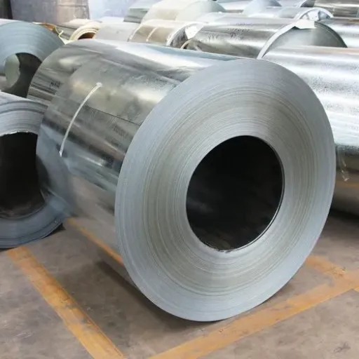
The Electrical Steel Slitting Process Explained
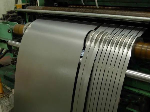
Electrical steel slitting is a precision longitudinal cutting process that transforms wide master coils of electrical steel or pure iron into multiple narrower strips of exact width. Unlike general-purpose steel cutting, electrical applications demand exceptional precision because the material's magnetic properties are extraordinarily sensitive to mechanical stress.
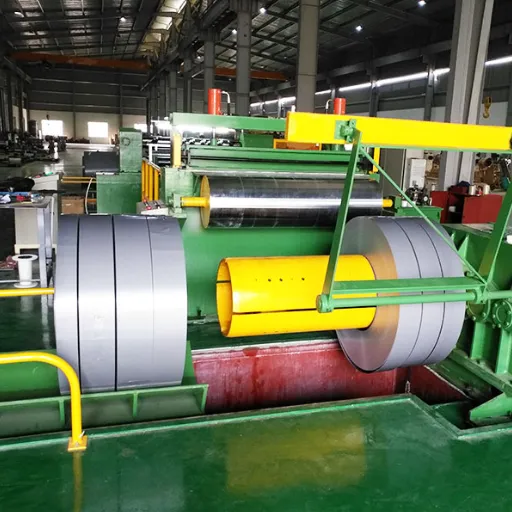
The electrical steel slitting process follows a carefully controlled sequence:
Uncoiling: Master coils up to 1,250mm wide mount on hydraulic uncoilers with expandable mandrels
Leveling: Multi-roll levelers remove residual coil set and internal stresses that could affect flatness
Slitting: Rotary carbide knives perform longitudinal cuts with blade clearances measured in microns
Tension control: Closed-loop systems maintain uniform strip tension to prevent distortion
Recoiling: Individual strips rewind under controlled torque into finished coils
For standard steel applications, achieving width tolerances of ±0.5mm might be perfectly acceptable. But when you're processing DT4C electromagnetic pure iron for high-efficiency transformer cores, that same tolerance variation could mean the difference between a 98.5% efficient unit and one that runs hot, wastes energy, and fails prematurely.
Why Electrical Applications Demand Superior Precision
When Marcus Chen, lead engineer at a Midwest transformer manufacturer, received a shipment of slit coils for a 500kVA distribution transformer project, the material looked perfect on paper. Same DT4C grade. Same 0.35mm thickness. Same certificate of analysis. But during core assembly, his team noticed something wrong—the laminations weren't stacking uniformly.
"The width variation was within the supplier's stated tolerance," Marcus explained. "But that ±0.3mm spread meant some packets had visible gaps. We had to shim the core to compensate, which added hours to assembly and compromised our stacking factor."
The core losses measured 18% higher than design calculations predicted. The culprit wasn't the base material—it was slitting precision that failed to meet the demands of high-performance electrical applications.
Electrical pure iron and silicon steel differ from general steels in one critical respect: their magnetic properties are the primary consideration, not mechanical strength. Every cut edge introduces plastic deformation and residual stresses that degrade permeability, increase coercivity, and raise core losses. The precision of that cutting process directly determines how much of the material's inherent magnetic capability survives into the final component.
How Slitting Precision Impacts Magnetic Properties
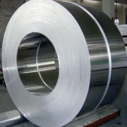
The Science of Magnetic Property Degradation
When rotary knives slit through electrical steel, they don't simply separate material—they fundamentally alter its structure near the cut edge. Research published in IEEE Transactions on Magnetics demonstrates that mechanical cutting introduces plastic deformation extending 0.5–1mm from the cut edge, creating a degraded zone where magnetic properties suffer significantly.
This degradation occurs through several mechanisms:
Work Hardening: The cutting process generates dislocations in the crystal structure, increasing hardness but reducing magnetic permeability. In the affected zone, coercivity can increase by 200–300% compared to the base material.
Residual Stresses: Mechanical deformation locks stresses into the material lattice. These stresses resist magnetic domain wall movement, increasing the energy required to magnetize and demagnetize the material—directly translating to higher hysteresis losses in transformer operation.
Edge Microstructure Changes: The heat and deformation at the cut edge can alter grain structure, particularly problematic for grain-oriented (CRGO) silicon steel where the directional structure is engineered specifically for magnetic flux alignment.
According to research from Graz University of Technology, the degradation follows a predictable profile: maximum impact at the edge, gradually recovering toward base material properties as distance from the cut increases. For precision slitting with proper parameters, this damaged zone might be limited to 0.2–0.3mm. With aggressive cutting—dull blades, excessive speed, or improper clearances—it can extend 1mm or more.
Quantified Performance Impact
The relationship between slitting quality and magnetic performance isn't theoretical—it's measurable and significant. Studies documented in MDPI Energies journal show that excessive mechanical tension during slitting can increase core losses by 20–30% in the affected material.
Consider what this means in practice:
A distribution transformer core with properly slit DT4C laminations might exhibit no-load losses of 280 watts at rated voltage. The same core design, built with poorly slit material showing edge degradation, could consume 350 watts or more—representing 70 watts of continuous waste over the transformer's 30+ year lifespan.
At 8,760 hours per year, that's 613 kWh of wasted energy annually. Across a utility fleet of 10,000 transformers, the cumulative waste exceeds 6 million kWh per year—equivalent to the annual consumption of roughly 600 households.
The damage isn't limited to energy waste. Degraded edges create localized flux disturbances that generate audible noise and thermal hotspots. Transformer noise regulations in many jurisdictions limit sound levels, meaning cores with poor-quality slit laminations may fail compliance testing even when material grades meet specifications.
Recovery Through Stress Relief Annealing
The good news: much of this damage is reversible. Post-slitting stress relief annealing, performed at 700–900°C in dry hydrogen or vacuum atmosphere, can recover approximately 90% of the original magnetic properties.
The annealing process accomplishes this through several mechanisms:
Recrystallization replaces work-hardened grains with new, stress-free crystal structures
Residual stresses relax as atoms rearrange into lower-energy configurations
Edge oxidation during annealing creates a thin iron oxide layer on any burrs, reducing their electrical conductivity and mitigating inter-laminar shorting
For high-efficiency transformers and precision magnetic components, stress relief annealing after slitting isn't optional—it's essential. Premium electrical pure iron coil slitting services should include annealing capability or coordination with annealing partners to deliver fully processed material ready for lamination stamping.
Need precision-slit coils with stress relief annealing? Contact our engineering team for specifications →
Critical Slitting Parameters for Electrical Coils
Width Tolerance Standards and Coil Slitting Tolerance
Coil slitting tolerance directly determines whether slit strips meet the exacting requirements of modern electrical steel applications.
Width tolerance requirements vary dramatically based on application. Understanding these distinctions ensures you specify appropriate precision levels—not paying for unnecessary tight tolerances on general applications, nor accepting inadequate precision for critical components.
Application | Typical Width | Standard Tolerance | Precision Tolerance |
|---|---|---|---|
Small relays/solenoids | 10–50mm | ±0.15mm | ±0.05mm |
Distribution transformer limbs | 100–230mm | ±0.20mm | ±0.10mm |
Power transformer yokes | 230–400mm | ±0.30mm | ±0.10mm |
Large power cores | 400–750mm | ±0.50mm | ±0.15mm |
For step-lap joint designs commonly used in modern distribution transformers, tighter coil slitting tolerance control becomes particularly important for transformer core lamination precision. Step-lap configurations depend on precise width relationships between adjacent laminations to create the overlapping joint pattern. Width variations cause visible step misalignment, reducing core efficiency and increasing magnetizing current.
Modern CNC-controlled electrical pure iron coil slitting lines achieve precision previously impossible. Laser-guided alignment systems maintain knife positioning accuracy within ±0.01mm (±10 microns), while automated feedback systems adjust for material thickness variations and temperature effects in real-time.
Slitting Burr Height Control
Burr formation represents one of the most insidious slitting quality issues because the visible strip might appear perfect while microscopic edge defects create serious performance problems. Burrs are raised metal projections extending above the strip surface along cut edges—essentially thin fins of displaced material created by the cutting action.
The problem isn't merely cosmetic. Research from Cardiff University demonstrates that burrs create unintended electrical contact between adjacent laminations when stacked in transformer cores. These contact points short-circuit the inter-laminar insulation, providing paths for eddy currents to flow between sheets rather than being confined within individual laminations.
The quantitative impact is significant. Testing with controlled artificial burrs showed that burr heights of just 15–20 microns produced measurable increases in specific total power loss. When burrs penetrate the thin insulation coating applied to electrical steel—typically just 1–3 microns thick—they create direct metal-to-metal contact that dramatically increases eddy current losses.
Industry standards for high-precision electrical applications specify maximum burr heights of:
Precision transformer laminations: <5 microns (<0.005mm)
Standard distribution transformers: <10–15 microns
General motor applications: <25 microns or <2% of material thickness
Achieving these slitting burr height control tolerances requires meticulous attention to blade condition, clearance settings, and cutting speed. Carbide knives require regular sharpening—typically every 200–500 tons depending on material hardness—and precise clearance adjustment based on material thickness.
Edge Quality and Camber Specifications
Beyond width and burrs, several additional edge characteristics affect performance:
Edge Condition: Clean, straight edges free from cracks, tearing, or work-hardened ridges are essential. Cracked edges create stress concentrations that propagate during core assembly and operation. Visual inspection under magnification should reveal smooth, continuous edge surfaces.
Camber: Longitudinal curvature, measured as deviation from straight over a defined length, must be controlled to ensure proper feeding in automated stamping equipment and flat stacking in cores. Typical specifications limit camber to ≤8mm over 4 meters for precision applications.
Edge Squareness: For mitred corner joints and certain lamination geometries, edge squareness to the strip longitudinal axis becomes critical. Tolerances of ±0.05mm ensure proper joint alignment in assembled cores.
Tension Management
Excessive mechanical tension during slitting represents the single largest controllable cause of magnetic property degradation. While some tension is necessary for web handling and proper coiling, tension levels must be minimized—particularly for high-permeability grades like DT4C.
Research consistently shows that high strip tension increases dislocation density and residual stresses, directly correlating with increased core losses. Modern slitting lines employ closed-loop tension control systems that monitor and adjust tension dynamically, typically maintaining variance within ±1% of setpoint.
For soft magnetic materials, tension should be kept to the minimum necessary for stable web transport. The material should never be stretched beyond its elastic limit, and looper-type slitting configurations that minimize tension variations are preferred for the most demanding applications.
The Connection Between Slitting and Transformer Performance
Stacking Factor Impact
The stacking factor—also called lamination factor or space factor—is a critical design parameter that directly affects transformer sizing and efficiency. Defined as the ratio of net iron cross-sectional area to gross core area, it accounts for insulation coatings, air gaps, and stacking irregularities.
Stacking Factor=Net Iron AreaGross Core AreaStacking Factor=Gross Core AreaNet Iron Area
Typical stacking factors range from 0.85 to 0.96 for silicon steel laminations, with high-precision cores achieving up to 0.97. What many designers don't realize is that slitting precision significantly influences achievable stacking factors.
Width variations cause laminations to stack unevenly. When one side of a core packet is even 0.2mm wider than the other, the cumulative effect across hundreds of laminations creates visible step patterns and air gaps. These gaps reduce effective iron area, forcing designers to specify larger core cross-sections to achieve required magnetic capabilities—increasing material costs, weight, and overall transformer size.
Maria Santos, a transformer design engineer with 15 years of experience, learned this lesson on a recent project. "We specified standard tolerance material to save on processing costs. During prototype assembly, our stacking factor measured 0.91 instead of the 0.95 we designed for. To maintain the rated kVA, we had to increase core diameter by 8mm. The material 'savings' were completely erased by increased steel weight and larger tank dimensions."
For high-efficiency distribution transformers targeting premium efficiency certifications, specifying tight width tolerances (±0.10mm) becomes essential to achieve the stacking factors (≥0.95) necessary for competitive no-load loss performance.
Core Losses and Efficiency
Transformer efficiency depends on managing two primary loss categories: no-load (core) losses and load (copper) losses. For distribution transformers operating continuously energized, no-load losses dominate lifecycle energy consumption because they occur 24/7 regardless of loading.
Core losses comprise:
Hysteresis Losses: Energy consumed reversing magnetic domains during each AC cycle. Minimized by using high-permeability, low-coercivity materials like DT4C pure iron.
Eddy Current Losses: Circulating currents induced within the core material by changing magnetic flux. Minimized by using thin laminations (typically 0.23–0.35mm), adding silicon to increase resistivity, and applying insulation coatings between laminations.
Slitting precision affects both loss mechanisms. Edge degradation increases local coercivity, raising hysteresis losses in the affected zone. Burrs and edge defects create inter-laminar shorts, providing paths for eddy currents to circulate between sheets rather than being confined within individual laminations—directly increasing eddy current losses.
Modern efficiency standards such as DOE 2016 in the United States and similar regulations globally mandate maximum allowable losses at 50% and 100% loading. Transformers using poorly slit laminations may struggle to meet these standards, particularly for premium efficiency (TP1, NEMA Premium) requirements.
Thermal and Acoustic Performance
Beyond efficiency metrics visible on nameplates, slitting quality affects operational characteristics that impact transformer lifespan and community acceptance.
Hotspot Formation: Localized losses from edge defects concentrate heat generation. Temperature rises of 10–20°C above design limits in hotspot regions accelerate insulation aging and can lead to premature failure. Infrared thermography of operating transformers often reveals temperature patterns correlated to lamination quality.
Noise Generation: Magnetic forces cause laminations to vibrate at twice the supply frequency (100Hz or 120Hz). Imperfect edges and burrs create uneven contact surfaces that amplify vibration and radiated noise. Transformer noise regulations in many European and Asian jurisdictions impose strict limits, making lamination quality critical for market acceptance.
For transformers installed in residential areas or noise-sensitive environments, the acoustic benefits of precision-slit laminations can be as important as efficiency improvements.
Best Practices for Electrical Pure Iron Coil Slitting
Equipment Requirements
Achieving electrical-grade slitting precision demands investment in appropriate equipment. Key capabilities include:
CNC Knife Positioning: Computer-controlled positioning systems achieve setup accuracy within microns, with automated adjustment eliminating human error in shim selection and knife spacing.
Laser Alignment: Laser-based edge guidance systems continuously monitor strip position and automatically adjust to maintain centerline tracking within ±0.1mm.
Real-Time Thickness Monitoring: Laser micrometers or eddy current sensors provide continuous thickness measurement with automatic feedback to knife clearance settings, compensating for material variations.
Precision Arbors: Hardened steel arbors (HRC 58–62) with minimal runout (<0.01mm TIR) ensure consistent blade positioning across the full coil width.
For electrical pure iron coil slitting of DT4C grade, equipment must also accommodate the material's softness. Unlike harder silicon steels, pure iron's low carbon content makes it more susceptible to edge deformation, requiring sharper blades and more precise clearances.
Process Optimization
Blade Clearance: Proper clearance between upper and lower knives depends on material thickness and hardness. General guidelines suggest 5–10% of material thickness for soft magnetic materials, but optimal settings require experimentation and ongoing adjustment as blades wear.
Speed Management: Cutting speed affects edge quality through heat generation and deformation mechanics. Lower speeds generally produce cleaner edges but reduce throughput. For high-purity electrical steel, speeds of 50–100 m/min typically balance quality and productivity.
Lubrication: Minimal lubrication prevents galling without contaminating the material. For pure iron intended for electrical applications, lubricants must be compatible with subsequent annealing processes—residue that carbonizes during heat treatment would compromise the ultra-low carbon specification.
Blade Maintenance: Carbide knives require regular sharpening intervals based on accumulated tonnage. Running dull blades increases edge deformation, burr formation, and magnetic degradation. Premium operations track knife wear and replace or resharpen before quality degrades.
Post-Slitting Treatments
Stress Relief Annealing: As discussed earlier, annealing after slitting recovers magnetic properties degraded by cutting stresses. For DT4C pure iron, annealing at 750–850°C in dry hydrogen atmosphere for 2–4 hours typically restores 85–90% of original permeability and reduces coercivity toward base material levels.
Insulation Coating: Electrical laminations require thin insulation coatings (typically 0.5–3 microns) to prevent inter-laminar eddy currents. Organic, inorganic, or hybrid coatings are applied after slitting and annealing, then cured at controlled temperatures.
Quality Testing: Comprehensive quality verification should include:
Dimensional inspection (width, thickness, camber)
Burr height measurement (profilometer or microscopy)
Edge quality examination
Magnetic testing (Epstein frame or single sheet tester) on sample strips
Coating weight and continuity verification
Looking for a supplier with full processing capabilities? Shanxi Jurun offers precision slitting plus stress relief annealing for DT4C pure iron →
Material Grades and Slitting Considerations
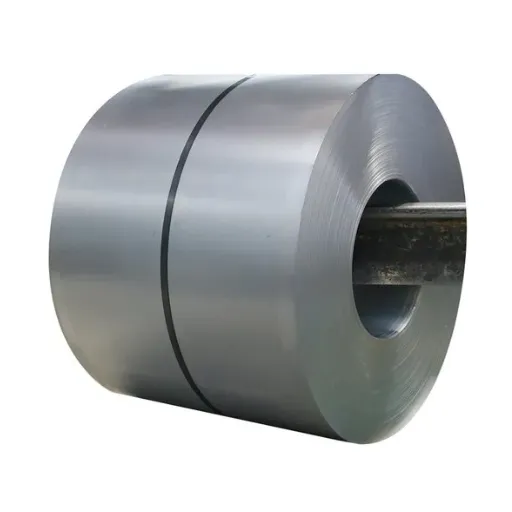
DT4C Pure Iron Specifications
DT4C represents the premium grade of electromagnetic pure iron per Chinese standard GB/T 6983, offering the highest magnetic permeability and lowest coercivity in the DT series. Its specifications make it ideal for high-efficiency transformers, precision relays, and sensitive magnetic instruments.
Key Specifications:
Carbon content: ≤0.004% (ultra-low carbon)
Coercivity (Hc): ≤32 A/m (guaranteed maximum)
Maximum permeability (μmax): ≥15.0 mH/m
Iron content: ≥99.9%
The ultra-low carbon content is particularly significant for slitting operations. Lower carbon means softer, more ductile material that cuts cleanly but requires sharper tooling. The tradeoff is worth it—DT4C's magnetic softness enables transformer designs with core losses 15–20% lower than standard DT4 material.
For slitting operations, DT4C requires:
Sharper blades changed more frequently
Tighter clearance control
Lower tension settings
Annealing after slitting for critical applications
CRGO vs. CRNGO Steel
While pure iron serves specific applications, most power transformers use silicon steel in two primary variants:
Cold Rolled Grain-Oriented (CRGO): Steel with directional grain structure optimized for magnetic flux flow in one direction. Used in transformer cores where flux follows predictable paths. Grade designations (M3, M4, M5, M6, Hi-B) indicate core loss characteristics—lower numbers mean lower losses.
CRGO slitting must preserve grain orientation alignment. Width tolerances are critical for step-lap joint designs common in modern transformers.
Cold Rolled Non-Grain-Oriented (CRNGO): Isotropic magnetic properties suitable for rotating machinery (motors, generators) where flux direction varies. Generally lower permeability than CRGO but more versatile for complex geometries.
CRNGO is more forgiving of slitting parameters but still requires precision for high-efficiency motor applications, particularly EV traction motors where efficiency directly affects vehicle range.
Choosing the Right Material and Precision Level
Not every application requires the tightest tolerances. Selecting appropriate precision levels optimizes cost without compromising performance:
Standard industrial motors: Standard slitting tolerances (±0.2mm) with conventional annealing
Distribution transformers: Precision slitting (±0.1mm) with stress relief annealing
High-efficiency transformers: High-precision slitting (±0.05mm) plus full annealing
Instrument transformers: Highest precision (±0.02mm) with specialized edge conditioning
Your material supplier should help evaluate the precision-cost tradeoff for your specific application rather than defaulting to the highest (and most expensive) precision level for every order.
Conclusion
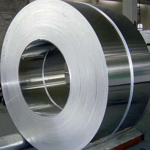
Slitting precision isn't merely a manufacturing detail—it's a fundamental determinant of electrical component performance. The data is unambiguous: poor slitting practices can increase core losses by 20–30%, compromise stacking factors, generate excess noise, and create thermal hotspots that shorten equipment life.
For engineers specifying materials and procurement managers evaluating suppliers, the key takeaways are clear:
Demand appropriate coil slitting tolerance: Match width tolerances to application requirements—±0.1mm for precision transformers, potentially ±0.2mm for general motor applications
Specify slitting burr height control limits: Insist on <10 micron burr heights for electrical applications, <5 microns for high-efficiency designs
Consider annealing: For premium grades like DT4C, stress relief annealing after electrical pure iron coil slitting recovers up to 90% of magnetic properties degraded by cutting
Verify capabilities: Not all slitting operations can achieve transformer core lamination precision—evaluate equipment, quality systems, and magnetic testing capabilities
The electrical steel market's growth to USD 84.6 billion by 2035 reflects increasing demand for efficient power distribution and electrification. Every watt of loss prevented through precision manufacturing contributes to global energy efficiency goals while reducing operational costs for end users.
When selecting electrical pure iron coil slitting services, you're not just buying cut metal—you're investing in magnetic performance that will persist for decades in energized transformer cores. Choose precision that matches your performance requirements.
Ready to optimize your transformer or motor designs with precision-slit DT4C pure iron? Contact Shanxi Jurun Technology for specifications, samples, and competitive pricing from China's pure iron production hub.
Shanxi Jurun Technology Co., Ltd. specializes in electromagnetic pure iron products including DT4C coils, precision slitting services, and stress relief annealing. Located in Taiyuan, Shanxi—the heart of China's pure iron industry—we supply manufacturers worldwide with materials meeting GB/T 6983, ASTM A848, and IEC 60404-2 standards.
Recently Posted
-
Industrial Pure Iron vs. Armco Iron: Terminology, History, and Modern Equivalents
September 2, 2026Not long ago, a European motor manufacturer opened an aging drawing for a magnetic shielding housing and found the material callou Read More
 -
Shanxi Jurun Technology: Your Electromagnetic Pure Iron Partner from Taiyuan, China's Pure Iron Prod
August 14, 2026When an international buyer searches for electromagnetic pure iron, they are not just looking for a material. They are looking for Read More
 -
Cold Drawing Process for Electromagnetic Pure Iron Wire: How Wire Rod Becomes Precision Cold-Drawn W
August 13, 2026Not long ago, a solenoid valve manufacturer in Italy received a shipment of 5.5 mm electromagnetic pure iron cold-drawn wire inten Read More
 -
How to Choose a Food Vacuum Sealer Supplier in China: 8 Evaluation Criteria
August 13, 2026An e-commerce brand owner in the UK contacted us some time ago after a supplier relationship fell apart. They had sourced roughly Read More

Contact Us
Recommended Products
-
 Seamless Tube With Good Cold Electrical Pure Iron Fittings Hot Workability for Forming Fittings and ConduitsNegotiableMOQ: 1 Ton
 -
Electromagnetic Pure Iron Forging for Automotive Sensor ManufacturingNegotiableMOQ: 100 Kilograms
-
Precision Cut Pure Iron Square Bar High Saturation Induction Raw Material for Generator and RotorNegotiableMOQ: 100 Kilograms
-
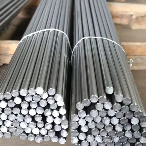
DT4C Super Grade Electromagnetic Pure Iron Bright Bar With Bundle Weight 30-100kg for Easy TransportationNegotiableMOQ: 1 Ton
-
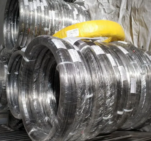
DT4C Electromagnetic Pure Iron Cold-Drawn Wire 0.5mm-6.0mm Diameter for TransformersNegotiableMOQ: 100 Kilograms
-
Industrial Pure Iron Bar for Electromagnetic Relay and Sensor ProductionNegotiableMOQ: 1 Ton
-
Electromagnetic Pure Iron Thin Sheet 0.3mm-0.8mm for Solenoid and Relay ManufacturingNegotiableMOQ: 500 Kilograms
-
Electrical Pure Iron Hot-Rolled Coil for Magnetic Components With Low Iron LossNegotiableMOQ: 1 Ton
-
Low Carbon DT4C Pure Iron Round Bar With 99.8% Fe Content for Electrical ApplicationsNegotiableMOQ: 1 Ton
-
Cold Rolled Pure Iron Slit Coil DT4C Grade Ultra Low Carbon ≤0.004% for Magnetic ComponentsNegotiableMOQ: 1 Ton
-
Low Iron Loss Electromagnetic Pure Iron Hot-Rolled Coil DT4C for Transformer CoresNegotiableMOQ: 1 Ton
-
Soft Magnetic Pure Iron Sheet With Minimum Iron Loss for High-Efficiency MotorsNegotiableMOQ: 1 Ton
-
Electromagnetic Pure Iron Cold Rolled Coil DT4C for High Magnetic Permeability ApplicationsNegotiableMOQ: 1 Ton
-
Industrial Pure Iron Tube Superior Surface Quality Electromagnetic Pure Iron Tube for Welding and Plating ProcessesNegotiableMOQ: 1 Ton
-
DT4 Seamless Pure Iron Tubing for High-Performance Electrical Equipment ApplicationsNegotiableMOQ: 1 Ton
-
DT4C Iron Wire Rod for Precision Magnetic Shielding ApplicationsNegotiableMOQ: 100 Kilograms
-
Industrial Pure Iron Fittings DT4 Pure Iron Seamless Tube With Low Hysteresis Loss for Electromagnetic SystemsNegotiableMOQ: 1 Ton
-
DT4C Cold Rolled Coil Slitting for Electrical Enclosure ManufacturingNegotiableMOQ: 1 Ton
-
Anti Rust Coated Pure Iron Square Bar Low Carbon Raw Material for Welding and Forging Magnetic PartsNegotiableMOQ: 100 Kilograms
-
DT4 Pure Iron Cold-Drawn Wire 0.5mm-6.0mm Diameter for Precision EngineeringNegotiableMOQ: 500 Kilograms